DTC B1423/23 Pressure Switch Circuit |
| DTC No. | DTC Detection Condition | Trouble Area |
| B1423/23 | Open or short in pressure switch circuit |
|
| 1.CHECK REFRIGERANT |
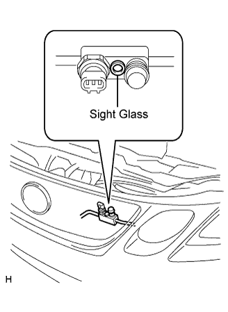 |
Check the sight glass of the cooler unit refrigerant liquid pipe.
Prepare the vehicle according to the chart below.
| Item | Condition |
| Vehicle Doors | Fully open |
| Temperature Setting | MAX COLD |
| Blower Speed | HI |
| A/C | ON |
Compare the sight glass to the following chart.
| Item | Symptom | Amount of Refrigerant | Corrective Actions |
| 1 | Bubbles visible | Insufficient* |
|
| 2 | No bubbles visible | Empty, insufficient or excessive | Refer to 3 and 4 |
| 3 | No temperature difference between compressor inlet and outlet | Empty or nearly empty |
|
| 4 | Considerable temperature difference between compressor inlet and outlet | Proper or excessive | Refer to 5 and 6 |
| 5 | Immediately after air conditioning is turned OFF, refrigerant clears | Excessive |
|
| 6 | Immediately after air conditioning is turned OFF, refrigerant foams and then becomes clear | Proper | - |
|
| ||||
| OK | |
| 2.READ VALUE OF INTELLIGENT TESTER |
Connect the intelligent tester to the DLC3.
Turn the engine switch on (IG) and push the intelligent tester main switch on.
Select the item below in the Data List, and read the display on the intelligent tester.
| Item | Measure Item / Display (Range) | Normal Condition | Diagnostic Note |
| Regulator Pressure Sensor (Reg Press Sens) | Regulator Pressure Sensor / Min.: 0, Max.: 255 | Actual regulator pressure is displayed | - |
| Regulator Control Current (Reg Ctrl Currnt) | Regulator Control Current / Min.: 0 A, Max.: 255 A | - | - |
| NG | A |
| OK (Checking from the PROBLEM SYMPTOMS TABLE) | B |
| OK (Checking from the DTC) | C |
|
| ||||
|
| ||||
| A | |
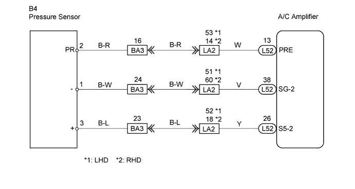
| 3.CHECK WIRE HARNESS (PRESSURE SENSOR - A/C AMPLIFIER) |
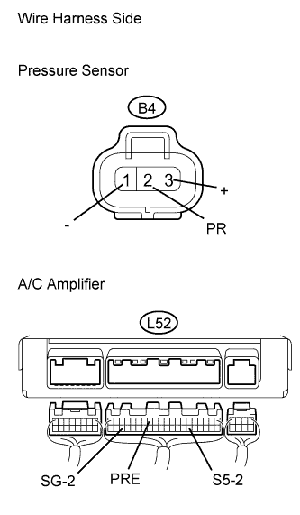 |
Disconnect the B4 pressure sensor connector.
Disconnect the L52 A/C amplifier connector.
Measure the resistance of the wire harness side connectors.
| Tester Connection | Condition | Specified Condition |
| B4-2 (PR) - L52-13 (PRE) | Always | Below 1 Ω |
| B4-3 (+) - L52-26 (S5-2) | Always | Below 1 Ω |
| B4-1 (-) - L52-38 (SG-2) | Always | Below 1 Ω |
| L52-13 (PRE) - Body ground | Always | 10 kΩ or higher |
| L52-26 (S5-2) - Body ground | Always | 10 kΩ or higher |
| L52-38 (SG-2) - Body ground | Always | 10 kΩ or higher |
|
| ||||
| OK | |
| 4.CHECK AIR CONDITIONING AMPLIFIER |
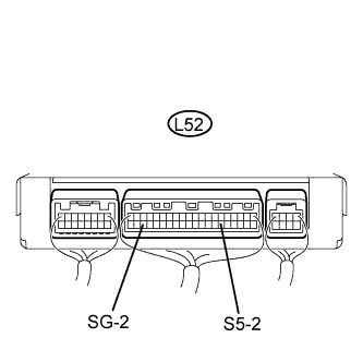 |
Remove the A/C amplifier with its connectors still connected.
Measure the resistance of the connector.
| Tester Connection | Condition | Specified Condition |
| L52-38 (SG-2) - Body ground | Always | Below 1 Ω |
Measure the voltage of the connector.
| Tester Connection | Condition | Specified Condition |
| L52-26 (S5-2) - Body ground | Engine switch on (IG) | 10 to 14 V |
| Engine switch off | Below 1 V |
|
| ||||
| OK | |
| 5.INSPECT PRESSURE SENSOR |
 |
Install the manifold gauge set.
Connect the three 1.5 V dry cell batteries' positive (+) lead to terminal 3 and the negative (-) lead to terminal 1. Then connect the voltmeter's positive (+) lead to terminal 2 and the negative (-) lead to terminal 1. Measure the voltage.
|
| ||||
| OK | ||
| ||
