DTC B2414 Steering Position Sensor Malfunction |
| DTC No. | DTC Detection Condition | Trouble Area |
| B2414 |
|
|
| 1.READ VALUE OF INTELLIGENT TESTER |
Connect the intelligent tester to the DLC3.
Turn the engine switch on (IG) and turn the intelligent tester main switch on.
Select the items below in the Data List, and read the displays on the intelligent tester.
| Item | Measurement Item / Display (Range) | Normal Condition | Diagnostic Note |
| Steer Sens Sig | Steering sensor signal value / -384°to -382.5° | Approx. 0° (When steering wheel is straight) | - |
| OK (When checking from PROBLEM SYMPTOMS TABLE) | A |
| OK (When checking from DIAGNOSTIC TROUBLE CODE CHART) | B |
| NG | C |
|
| ||||
|
| ||||
| A | ||
| ||
| 2.CHECK DTC (ABS WITH EBD & BA & TRAC & VSC SYSTEM) |
Check the DTC of ABS with EBD & BA & TRAC & VSC system.
|
| ||||
| OK | |
| 3.CHECK VEHICLE CONDITION |
Check vehicle condition.
| w/o Variable steering gear ratio control | A |
| w/ Variable steering gear ratio control | B |
|
| ||||
| A | |
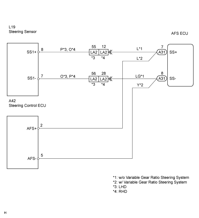
| 4.CHECK WIRE HARNESS (STEERING SENSOR - AFS ECU) |
 |
Disconnect the L19 steering sensor connector .
Disconnect the A31 AFS ECU connector.
Measure the resistance of the wire harness side connectors.
| Tester Connection | Condition | Specified Condition |
| L19-7 (SS1-) - A31-8 (SS-) | Always | Below 1 Ω |
| L19-8 (SS1+) - A31-7 (SS+) | Always | Below 1 Ω |
| A31-8 (SS1-) - Body ground | Always | 10 kΩ or higher |
| A31-7 (SS1+) - Body ground | Always | 10 kΩ or higher |
|
| ||||
| OK | |
| 5.CHECK AFS ECU |
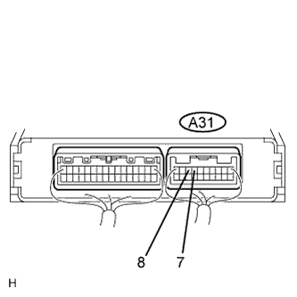 |
Reconnect the L19 steering sensor connector.
Reconnect the A31 AFS ECU connector.
Measure the voltage of the connector.
| Tester Connection | Condition | Specified Condition |
| A31-7 (SS+) - A31-8 (SS-) | Engine switch on (IG) | 0 to 5 V (Pulse generation) |
| OK (When checking from DIAGNOSTIC TROUBLE CODE CHART) | A |
| OK (When checking from PROBLEM SYMPTOMS TABLE) | B |
| NG | C |
|
| ||||
|
| ||||
| A | ||
| ||
| 6.CHECK WIRE HARNESS (STEERING CONTROL ECU - AFS ECU) |
 |
Disconnect the A42 steering control ECU connector.
Disconnect the A31 AFS ECU connector.
Measure the resistance of the wire harness side connectors.
| Tester Connection | Condition | Specified Condition |
| A42-5 (AFS-) - A31-8 (SS-) | Always | Below 1 Ω |
| A42-2 (AFS+) - A31-7 (SS+) | Always | Below 1 Ω |
| A31-8 (SS1-) - Body ground | Always | 10 kΩ or higher |
| A31-7 (SS1+) - Body ground | Always | 10 kΩ or higher |
|
| ||||
| OK | |
| 7.CHECK AFS ECU |
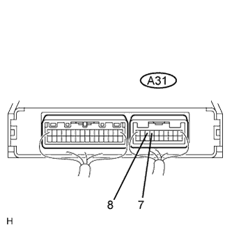 |
Reconnect the A31 AFS ECU connector.
Measure the voltage of the connector.
| Tester Connection | Condition | Specified Condition |
| A31-7 (SS+) - A31-8 (SS-) | Engine switch on (IG) | 0 to 5 V (Pulse generation) |
| OK (When checking from DIAGNOSTIC TROUBLE CODE CHART) | A |
| OK (When checking from PROBLEM SYMPTOMS TABLE) | B |
| NG | C |
|
| ||||
|
| ||||
| A | ||
| ||
