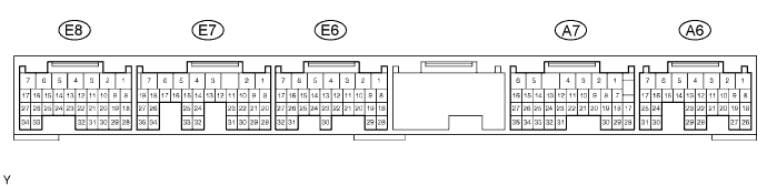
SFI SYSTEM > TERMINALS OF ECM |
| Symbols (Terminal No.) | Wiring Color | Terminal Description | Condition | Specified Condition |
| BATT (A6-4) - E1 (E7-7) | L - BR | Battery (for measuring battery voltage and for the ECM memory) | Always | 9 to 14 V |
| +BM (E8-5) - ME01 (E8-4) | P - BR | Power source of throttle motor | Always | 9 to 14 V |
| IGSW (A6-17) - E1 (E7-7) | B-W - BR | Engine switch | Engine switch on (IG) | 9 to 14 V |
| +B (A6-6) - E1 (E7-7) | B-R - BR | Power source of ECM | Engine switch on (IG) | 9 to 14 V |
| +B1 (A6-5) - E1 (E7-7) | B-R - BR | Power source of ECM | Engine switch on (IG) | 9 to 14 V |
| VC (E8-29) - E2 (E8-28) | L-Y - BR | Power source of sensor (specific voltage) | Engine switch on (IG) | 4.5 to 5.5 V |
| VTA (E8-23) - E2 (E8-28) | R-L - BR | Throttle position sensor (for engine control) | Engine switch on (IG), accelerator pedal fully released | 0.5 to 1.2 V |
| VTA (E8-23) - E2 (E8-28) | R-L - BR | Throttle position sensor (for engine control) | Engine switch on (IG), accelerator pedal fully depressed | 3.2 to 4.8 V |
| VTA2 (E8-22) - E2 (E8-28) | L-B - BR | Throttle position sensor (for sensor malfunction detection) | Engine switch on (IG), accelerator pedal fully released | 2.1 to 3.1 V |
| VTA2 (E8-22) - E2 (E8-28) | L-B - BR | Throttle position sensor (for sensor malfunction detection) | Engine switch on (IG), accelerator pedal fully depressed | 4.5 to 5.5 V |
| VPA (A7-33) - EPA (A7-34) | G-W - L-Y | Accelerator pedal position sensor (for engine control) | Engine switch on (IG), accelerator pedal fully released | 0.5 to 1.1 V |
| VPA (A7-33) - EPA (A7-34) | G-W - L-Y | Accelerator pedal position sensor (for engine control) | Engine switch on (IG), accelerator pedal fully depressed | 2.6 to 4.5 V |
| VPA2 (A7-32) - EPA2 (A7-26) | P-L - BR | Accelerator pedal position sensor (for sensor malfunction detection) | Engine switch on (IG), accelerator pedal fully released | 1.2 to 2.0 V |
| VPA2 (A7-32) - EPA2 (A7-26) | P-L - BR | Accelerator pedal position sensor (for sensor malfunction detection) | Engine switch on (IG), accelerator pedal fully depressed | 3.4 to 5.3 V |
| VCPA (A7-35) - EPA (A7-34) | P - L-Y | Power source of accelerator pedal position sensor (for VPA) | Engine switch on (IG) | 4.5 to 5.5 V |
| VCP2 (A7-27) - EPA2 (A7-26) | LG - BR | Power source of accelerator pedal position sensor (for VPA2) | Engine switch on (IG) | 4.5 to 5.5 V |
| VG (E6-27) - E2G (E6-26) | G-B - B-W | MAF meter | Idling, shift position P or N, A/C switch off | 0.5 to 3.0 V |
| THA (E6-25) - E2 (E8-28) | G - BR | IAT sensor | Idling, IAT: 0 to 80°C (32 to 176°F) after warm-up | 0.5 to 3.4 V |
| THW (E6-20) - E2 (E8-28) | R - BR | ECT sensor | Idling, ECT: 60 to 100°C (140 to 212°F) after warm-up | 0.2 to 1.0 V |
| STA (A6-12) - E1 (E7-7) | R - BR | Starter signal | Cranking (shift position P or N position and engine switch start) | 6 V or more |
| #1 (E8-15) - E01 (E6-2) #2 (E6-17) - E01 (E6-2) #3 (E8-14) - E01 (E6-2) #4 (E6-16) - E01 (E6-2) #5 (E8-13) - E01 (E6-2) #6 (E6-15) - E01 (E6-2) #7 (E8-12) - E01 (E6-2) #8 (E6-14) - E01 (E6-2) | Y-B - W-B B-Y - W-B R-W - W-B LG - W-B L-W - W-B R - W-B G-W - W-B B-L - W-B | Injector | Idling | Pulse generation (see waveform 1) |
| #1 (E8-15) - E01 (E6-2) #2 (E6-17) - E01 (E6-2) #3 (E8-14) - E01 (E6-2) #4 (E6-16) - E01 (E6-2) #5 (E8-13) - E01 (E6-2) #6 (E6-15) - E01 (E6-2) #7 (E8-12) - E01 (E6-2) #8 (E6-14) - E01 (E6-2) | Y-B - W-B B-Y - W-B R-W - W-B LG - W-B L-W - W-B R - W-B G-W - W-B B-L - W-B | Injector | Engine switch on (IG) | 9 to 14 V |
| IGT1 (E8-17) - E1 (E7-7) IGT2 (E6-13) - E1 (E7-7) IGT3 (E8-16) - E1 (E7-7) IGT4 (E6-12) - E1 (E7-7) IGT5 (E8-27) - E1 (E7-7) IGT6 (E6-11) - E1 (E7-7) IGT7 (E8-26) - E1 (E7-7) IGT8 (E6-10) - E1 (E7-7) | L-R - BR L-B - BR V - BR P-L - BR W-L - BR W-L - BR LG-B - BR L-W - BR | Ignition coil and igniter (ignition signal) | Idling | Pulse generation (see waveform 2) |
| IGF1 (E6-7) - E1 (E7-7) IGF2 (E6-6) - E1 (E7-7) | G-B - BR R - BR | Ignition coil and igniter (ignition confirmation signal) | Idling | Pulse generation (see waveform 2) |
| IGF1 (E6-7) - E1 (E7-7) IGF2 (E6-6) - E1 (E7-7) | G-B - BR R - BR | Ignition coil and igniter (ignition confirmation signal) | Engine switch on (IG) | 4.5 to 5.5 V |
| G2 (E8-21) - G2- (E8-20) | Y - L | Camshaft position sensor | Idling | Pulse generation (see waveform 3) |
| NE+ (E8-32) - NE- (E8-31) | R - G | Crankshaft position sensor | Idling | Pulse generation (see waveform 3) |
| MREL (A6-13) - E1 (E7-7) | Y - BR | EFI MAIN relay | Engine switch on (IG) | 9 to 14 V |
| MREL (A6-13) - E1 (E7-7) | Y - BR | EFI MAIN relay | Engine switch off (for 3 seconds or more) | Below 1.5 V |
| FPR (A6-15) - E01 (E6-2) | R-W - W-B | F/PMP relay | Engine switch on (IG) | Below 3 V |
| FPR (A6-15) - E01 (E6-2) | R-W - W-B | F/PMP relay | Cranking | 6 to 14 V |
| FC (A6-14) - E01 (E6-2) | R-G - W-B | Fuel pump control | Engine switch on (IG) | 9 to 14 V |
| FC (A6-14) - E01 (E6-2) | R-G - W-B | Fuel pump control | Idling after engine warm-up | Below 3 V |
| STP (A7-4) - E1 (E7-7) | R-B - BR | Stop light switch | Brake pedal is depressed | 7.5 to 14 V |
| STP (A7-4) - E1 (E7-7) | R-B - BR | Stop light switch | Brake pedal is released | Below 1.5 V |
| ST1- (A6-8) - E1 (E7-7) | G-W - BR | Stop light switch (opposite to STP terminal) | Engine switch on (IG) Brake pedal is depressed | Below 1.5 V |
| ST1- (A6-8) - E1 (E7-7) | G-W - BR | Stop light switch (opposite to STP terminal) | Engine switch on (IG) Brake pedal is released | 7.5 to 14 V |
| PRG (E8-11) - E01 (E6-2) | W - W-B | VSV for EVAP | Engine switch on (IG) and engine stopped | 9 to 14 V |
| PRG (E8-11) - E01 (E6-2) | W - W-B | VSV for EVAP | Idling after engine warm-up | Pulse generation (see waveform 4) |
| OX1A (E8-30) - O1A- (E8-25) OX2A (E6-28) - O2A- (E6-21) | B - BR W - BR | Heated oxygen sensor (bank 1, 2 sensor 1) | Idling | 0.1 to 0.9 V Pulse generation (see waveform 5) |
| OX1B (A7-28) - O1B- (A7-29) OX2B (A7-17) - O2B- (A7-18) | W - LG-R B - G | Heated oxygen sensor (bank 1, 2 sensor 2) | Idling | 0.1 to 0.9 V Pulse generation (see waveform 6) |
| HT1A (E8-24) - E03 (E8-6) HT1B (A7-2) - E03 (E8-6) HT2A (E6-5) - E03 (E8-6) HT2B (A7-1) - E03 (E8-6) | B-W - W-B Y-B - W-B L-W - W-B L-W - W-B | Heated oxygen sensor heater | Idling | Below 3.0 V |
| HT1A (E8-24) - E03 (E8-6) HT1B (A7-2) - E03 (E8-6) HT2A (E6-5) - E03 (E8-6) HT2B (A7-1) - E03 (E8-6) | B-W - W-B Y-B - W-B L-W - W-B L-W - W-B | Heated oxygen sensor heater | Engine switch on (IG) | 9 to 14 V |
| KNK1 (E7-28) - EKNK (E7-30) | W - B | Knock sensor (bank 1) | Maintain engine RPM at 4,000 rpm after engine warmed-up | Pulse generation (see waveform 7) |
| KNK2 (E7-29) - EKN2 (E7-31) | R - G | Knock sensor (bank 2) | Maintain engine RPM at 4,000 rpm after engine warmed-up | Pulse generation (see waveform 7) |
| TC (A7-3) - E1 (E7-7) | V - BR | Terminal TC of DLC3 | Engine switch on (IG) | 9 to 14 V |
| W (A7-8) - E1 (E7-7) | R-L - BR | MIL | Idling | 9 to 14 V |
| W (A7-8) - E1 (E7-7) | R-L - BR | MIL | Engine switch on (IG) | Below 3.0 V |
| VV1+ (E8-19) - VV1- (E8-18) | R - G | Variable Valve Timing (VVT) sensor (bank 1) | Idling | Pulse generation (see waveform 8) |
| VV2+ (E6-19) - VV2- (E6-18) | Y - L | VVT sensor (bank 2) | Idling | Pulse generation (see waveform 8) |
| OC1+ (E8-34) - OC1- (E8-33) | R-B - L-R | Camshaft timing control valve (OCV) (bank 1) | Accelerate slowly after engine warmed-up | Pulse generation (see waveform 9) |
| OC2+ (E6-9) - OC2- (E6-8) | W - Y-B | OCV (bank 2) | Accelerate slowly after engine warmed-up | Pulse generation (see waveform 9) |
| TACH (A7-16) - E1 (E7-7) | W-L - BR | Engine speed | Idling | Pulse generation (see waveform 10) |
| ACIS (E6-3) - E01 (E6-2) | Y - W-B | Vacuum switching valve (for ACIS) | Engine switch on (IG) | 9 to 14 V |
| ACIS (E6-3) - E01 (E6-2) | Y - W-B | Vacuum switching valve (for ACIS) | Engine RPM: 2,500 to 4,000 rpm and throttle opening angle: 40% or more | Below 3.0 V |
| M+ (E8-2) - ME01 (E8-4) | B - BR | Throttle actuator | Idling | Pulse generation (see waveform 11) |
| M- (E8-1) - ME01 (E8-4) | W - BR | Throttle actuator | Idling | Pulse generation (see waveform 12) |
| SPD (A6-22) - E1 (E7-7) | V-W - BR | Speed signal from combination meter | Engine switch on (IG), rotate driving wheel slowly | Pulse generation (see waveform 13) |
| RFC (A6-10) - E1 (E7-7) | G-Y - BR | Cooling fan ECU | Engine switch on (IG) | 0 to 3 V |
| E1 (E7-7) - Body ground | BR - N/A | Ground | Always | Below 1 Ω |
| CANH (A6-25) - E1 (E7-7) | R - BR | CAN communication line | Engine switch on (IG) | Pulse generation (see waveform 14) |
| CANL (A6-24) - E1 (E7-7) | W - BR | CAN communication line | Engine switch on (IG) | Pulse generation (see waveform 15) |
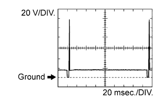
| WAVEFORM 1 |
 |
| Item | Content |
| Symbols (Terminal No.) | #1 (E8-15) - E01 (E6-2) #2 (E6-17) - E01 (E6-2) #3 (E8-14) - E01 (E6-2) #4 (E6-16) - E01 (E6-2) #5 (E8-13) - E01 (E6-2) #6 (E6-15) - E01 (E6-2) #7 (E8-12) - E01 (E6-2) #8 (E6-14) - E01 (E6-2) |
| Tester Range | 20 V/DIV., 20 msec./DIV. |
| Condition | Idling |
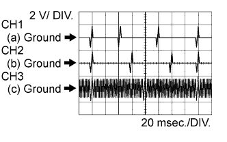
| WAVEFORM 2 |
 |
| Item | Content |
| Symbols (Terminal No.) | (a) IGT1 (E8-17) - E1 (E7-7) (a) IGT2 (E6-13) - E1 (E7-7) (a) IGT3 (E8-16) - E1 (E7-7) (a) IGT4 (E6-12) - E1 (E7-7) (a) IGT5 (E8-27) - E1 (E7-7) (a) IGT6 (E6-11) - E1 (E7-7) (a) IGT7 (E8-26) - E1 (E7-7) (a) IGT8 (E6-10) - E1 (E7-7) (b) IGF1 (IGF2) and E1 |
| Tester Range | 2 V/DIV., 20 msec./DIV. |
| Condition | Idling |
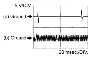
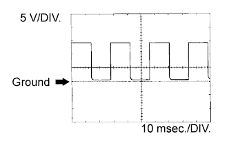
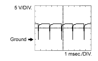
| WAVEFORM 3 |
 |
| Item | Content |
| Symbols (Terminal No.) | (a) G2 (E8-21) - G2- (E8-20) (b) NE+ (E8-32) - NE- (E8-31) |
| Tester Range | 5 V/DIV., 20 msec./DIV. |
| Condition | Idle after engine warmed-up |
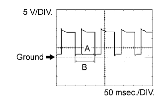
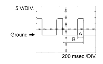
| WAVEFORM 4 |
 |
| Item | Content |
| Symbols (Terminal No.) | PRG (E8-11) - E01 (E6-2) |
| Tester Range | 5 V/DIV., 50 msec./DIV. |
| Condition | Accelerated slowly after engine warmed-up |
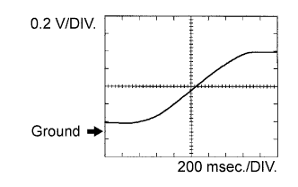
| WAVEFORM 5 |
 |
| Item | Content |
| Symbols (Terminal No.) | OX1A (E8-30) - O1A- (E8-25) OX2A (E6-28) - O2A- (E6-21) |
| Tester Range | 0.2 V/DIV., 200 msec./DIV. |
| Condition | Maintain engine speed at 2,500 rpm after engine warmed-up |
| WAVEFORM 6 |
 |
| Item | Content |
| Symbols (Terminal No.) | OX1B (A7-28) - O1B- (A7-29) OX2B (A7-17) - O2B- (A7-18) |
| Tester Range | 0.2 V/DIV., 200 msec./DIV. |
| Condition | Maintain engine speed at 2,500 rpm after engine warmed-up |
| WAVEFORM 7 |
 |
| Item | Content |
| Symbols (Terminal No.) | KNK1 (E7-28) - EKNK (E7-30) KNK2 (E7-29) - EKN2 (E7-31) |
| Tester Range | 1 V/DIV., 1 msec./DIV. |
| Condition | Maintain engine speed at 2,000 rpm after engine warmed-up |
| WAVEFORM 8 |
 |
| Item | Content |
| Symbols (Terminal No.) | (a) VV1+ (E8-19) - VV1- (E8-18) (b) VV2+ (E6-19) - VV2- (E6-18) (c) NE+ (E8-32) - NE- (E8-31) |
| Tester Range | 2 V/DIV., 20 msec./DIV. |
| Condition | Idle after engine warmed-up |
| WAVEFORM 9 |
 |
| Item | Content |
| Symbols (Terminal No.) | OC1+ (E8-34) - OC1- (E8-33) OC2+ (E6-9) - OC2- (E6-8) |
| Tester Range | 5 V/DIV., 200 msec./DIV. |
| Condition | Accelerated slowly after engine warmed-up |
| WAVEFORM 10 |
 |
| Item | Content |
| Symbols (Terminal No.) | TACH (A7-16) - E1 (E7-7) |
| Tester Range | 5 V/DIV., 10 msec./DIV. |
| Condition | Idling |
| WAVEFORM 11 |
 |
| Item | Content |
| Symbols (Terminal No.) | M+ (E8-2) - ME01 (E8-4) |
| Tester Range | 5 V/DIV., 1 msec./DIV. |
| Condition | Idle after engine warmed-up |
| WAVEFORM 12 |
 |
| Item | Content |
| Symbols (Terminal No.) | M- (E8-1) - ME01 (E8-4) |
| Tester Range | 5 V/DIV., 1 msec./DIV. |
| Condition | Idle after engine warmed-up |
| WAVEFORM 13 |
 |
| Item | Content |
| Symbols (Terminal No.) | SPD (A6-22) - E1 (E7-7) |
| Tester Range | 2 V/DIV., 20 msec./DIV. |
| Condition | Driving at 20 km/h (12 mph) |
| WAVEFORM 14 |
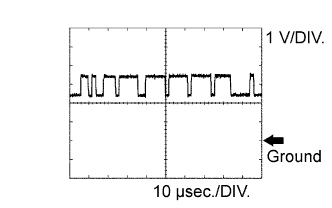 |
| Item | Content |
| Symbols (Terminal No.) | CANH (A6-25) - E1 (E7-7) |
| Tester Range | 1 V/DIV., 10 μsec./DIV. |
| Condition | Engine switch on (IG) |
| WAVEFORM 15 |
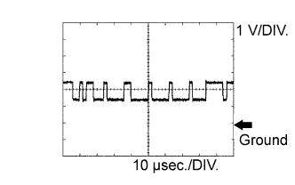 |
| Item | Content |
| Symbols (Terminal No.) | CANL (A6-24) - E1 (E7-7) |
| Tester Range | 1 V/DIV., 10 μsec./DIV. |
| Condition | Engine switch on (IG) |
