POWER WINDOW CONTROL SYSTEM > Remote Up / Down Function does not Operate |


| 1.CHECK MANUAL UP/DOWN FUNCTION |
Check that the manual UP/DOWN function of each switch operates normally.
|
| ||||
| OK | |
| 2.CHECK AUTO UP/DOWN FUNCTION |
Check that the AUTO UP/DOWN function of each switch operates normally.
|
| ||||
| OK | |
| 3.READ VALUE OF INTELLIGENT TESTER |
Check the Data List for proper functioning of the power window switch on the master switch.
| Item | Measurement Item / Display (Range) | Normal Condition | Diagnostic Note |
| P Door P/W Auto SW | Front passenger side power window switch AUTO UP/DOWN signal/ ON or OFF | ON: Front passenger side power window AUTO switch operates OFF: Front passenger side power window AUTO switch does not operate | - |
| P Door P/W Up SW | Front passenger side power window switch UP signal/ ON or OFF | ON: Front passenger side power window manual UP switch operates OFF: Front passenger side power window manual UP switch does not operate | - |
| P Door P/W Down SW | Front passenger side power window switch DOWN signal/ ON or OFF | ON: Front passenger side power window manual DOWN switch operates OFF: Front passenger side power window manual DOWN switch does not operate | - |
| Rl Door P/W Auto SW | Rear power window LH switch AUTO UP/DOWN signal/ ON or OFF | ON: Rear power window LH AUTO switch operates OFF: Rear power window LH AUTO switch does not operate | - |
| Rl Door P/W Up SW | Rear power window LH switch UP signal/ ON or OFF | ON: Rear power window LH manual UP switch operates OFF: Rear power window LH manual UP switch does not operate | - |
| Rl Door P/W Down SW | Rear power window LH switch DOWN signal/ ON or OFF | ON: Rear power window LH manual DOWN switch operates OFF: Rear power window LH manual DOWN switch does not operate | - |
| Rr Door P/W Auto SW | Rear power window RH switch AUTO UP/DOWN signal/ ON or OFF | ON: Rear power window RH AUTO switch operates OFF: Rear power window RH AUTO switch does not operate | - |
| Rr Door P/W Up SW | Rear power window RH switch UP signal/ ON or OFF | ON: Rear power window RH manual UP switch operates OFF: Rear power window RH manual UP switch does not operate | - |
| Rr Door P/W Down SW | Rear power window RH switch DOWN signal/ ON or OFF | ON: Rear power window RH manual DOWN switch operates OFF: Rear power window RH manual DOWN switch does not operate | - |
|
| ||||
| OK | ||
| ||
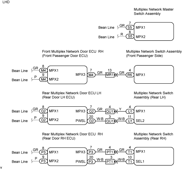
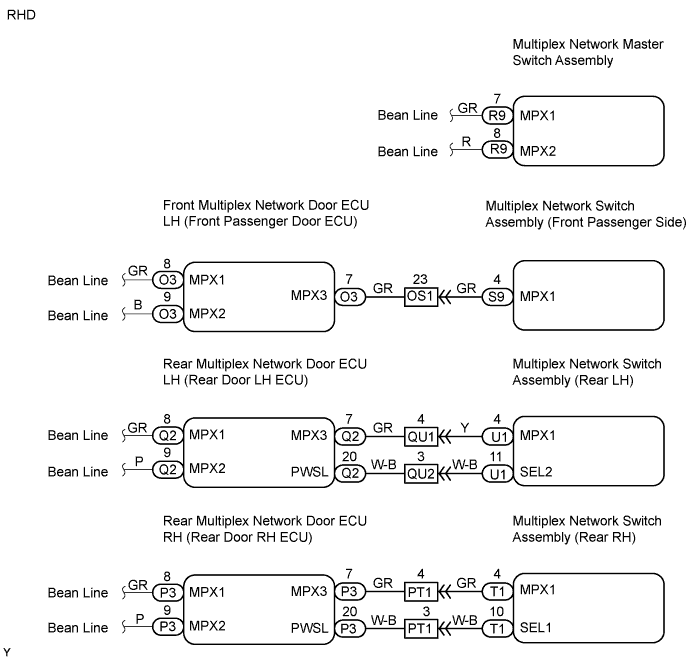
| 4.CHECK WIRE HARNESS (MULTIPLEX NETWORK DOOR ECU - MULTIPLEX NETWORK SWITCH ASSEMBLY ) |
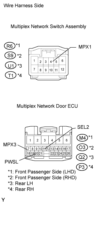 |
Disconnect the R6*1 or S9*2 and the U1 or T1 switch connector.
Disconnect the M4*1 or O3*2, Q2 or P3 ECU connector.
Measure the resistance of the wire harness side connectors.
| Tester Connection | Specified Condition |
| R6-4 (MPX1) - M4-7 (MPX3) | Below 1 Ω |
| R6-4 (MPX1) or M4-7 (MPX3) - Body ground | 10 kΩ or higher |
| Tester Connection | Specified Condition |
| S9-4 (MPX1) - O3-7 (MPX3) | Below 1 Ω |
| S9-4 (MPX1) or O3-7 (MPX3) - Body ground | 10 kΩ or higher |
| Tester Connection | Specified Condition |
| U1-4 (MPX1) - Q2-7 (MPX3) | Below 1 Ω |
| U1-11 (SEL2) - Q2-20 (PWSL) | Below 1 Ω |
| U1-4 (MPX1) or Q2-7 (MPX3) - Body ground | 10 kΩ or higher |
| U1-11 (SEL2) or Q2-20 (PWSL) - Body ground | 10 kΩ or higher |
| Tester Connection | Specified Condition |
| T1-4 (MPX1) - P3-7 (MPX3) | Below 1 Ω |
| T1-11 (SEL2) - P3-20 (PWSL) | Below 1 Ω |
| T1-4 (MPX1) or P3-7 (MPX3) - Body ground | 10 kΩ or higher |
| T1-11 (SEL2) or P3-20 (PWSL) - Body ground | 10 kΩ or higher |
|
| ||||
| OK | |
| 5.READ VALUE OF INTELLIGENT TESTER (WINDOW LOCK SIGNAL) |
Check the Data List for proper functioning of the power window switch on the master switch.
| Item | Measurement Item / Display (Range) | Normal Condition | Diagnostic Note |
| Power Window Lock SW | Power window lock switch signal/ ON or OFF | ON: Power window lock switch ON OFF: Power window lock switch OFF | - |
|
| ||||
| OK | ||
| ||
| 6.CHECK WIRE HARNESS (MASTER SWITCH ASSEMBLY - SWITCH ASSEMBLY) |
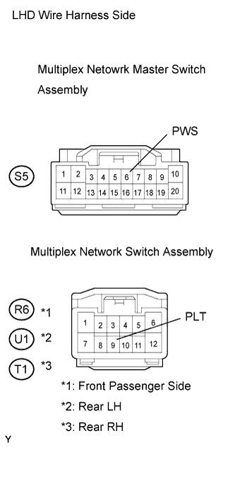 |
Disconnect the S5 or R9 switch connector.
Disconnect the R6 or S9, and the U1 or T1 switch connectors.
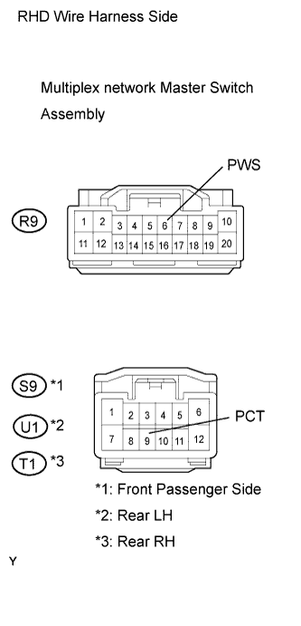 |
Measure the resistance of the wire harness side connectors.
| Tester Connection | Specified Condition |
| S5-6 (PWS) - R6-9 (PCT) | Below 1 Ω |
| S5-6 (PWS) or R6-9 (PCT) - Body ground | 10 kΩ or higher |
| Tester Connection | Specified Condition |
| S5-6 (PWS) - U1-9 (PCT) | Below 1 Ω |
| S5-6 (PWS) or U1-9 (PCT) - Body ground | 10 kΩ or higher |
| Tester Connection | Specified Condition |
| S5-6 (PWS) - T1-9 (PCT) | Below 1 Ω |
| S5-6 (PWS) or T1-9 (PCT) - Body ground | 10 kΩ or higher |
| Tester Connection | Specified Condition |
| R9-6 (PWS) - S9-9 (PCT) | Below 1 Ω |
| S9-6 (PWS) or S9-9 (PCT) - Body ground | 10 kΩ or higher |
| Tester Connection | Specified Condition |
| R9-6 (PWS) - U1-9 (PCT) | Below 1 Ω |
| R9-6 (PWS) or U1-9 (PCT) - Body ground | 10 kΩ or higher |
| Tester Connection | Specified Condition |
| R9-6 (PWS) - T1-9 (PCT) | Below 1 Ω |
| R9-6 (PWS) or T1-9 (PCT) - Body ground | 10 kΩ or higher |
|
| ||||
| OK | ||
| ||
