OIL PUMP > INSTALLATION |
| 1. INSTALL TIMING CHAIN OR BELT COVER SUB-ASSEMBLY |
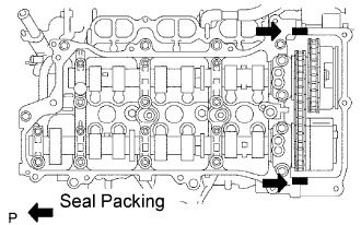
Apply seal packing in a continuous bead to the engine unit as shown in the following illustration.
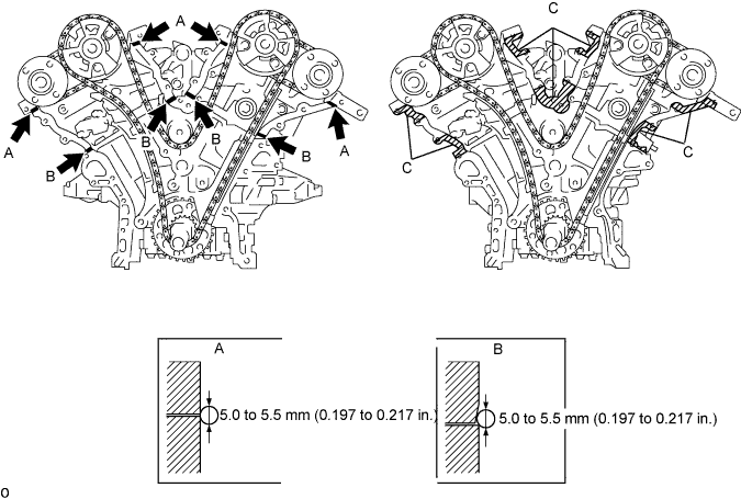
Apply seal packing in a continuous bead to the timing chain cover as shown in the following illustration.
| Area | Seal Packing Diameter | Application Position from Inside Seal Line |
| Continuous Line Area | 3.5 to 4.0 mm (0.138 to 0.158 in.) | 3.0 to 4.0 mm (0.118 to 0.158 in.) |
| Alternate Long and Short Dashed Line Area | 3.5 to 4.0 mm (0.138 to 0.158 in.) | 2.0 to 3.0 mm (0.079 to 0.118 in.) |
| Dashed Line Area | 4.0 to 5.0 mm (0.158 to 0.197 in.) | 1.0 to 2.0 mm (0.039 to 0.079 in.) |

 |
Install a new gasket.
 |
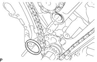
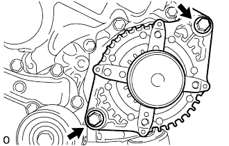
Align the oil pump drive rotor spline and the crankshaft as shown in the illustration. Install the spline and chain cover to the crankshaft.
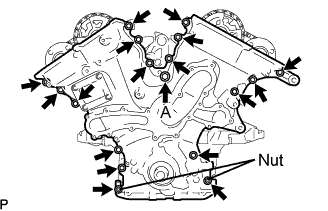 |
Install the timing chain cover with the 16 bolts and 2 nuts. Uniformly tighten the bolts and nuts in several passes.
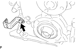 |
Install the wiring harness bracket with the bolt.
| 2. INSTALL CYLINDER HEAD COVER SUB-ASSEMBLY RH (for Bank 1) |
 |
Apply seal packing as shown in the illustration.
Install the gasket to the head cover.
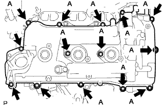 |
Install the head cover with the 14 bolts.
| 3. INSTALL CYLINDER HEAD COVER SUB-ASSEMBLY LH (for Bank 2) |
 |
Apply seal packing as shown in the illustration.
Install the gasket to the head cover.
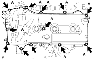 |
Install the head cover with the 14 bolts.
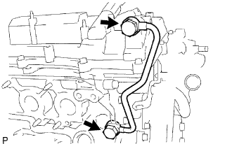
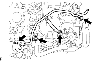
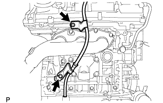
| 4. INSTALL NO. 2 OIL PIPE |
 |
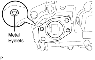
Make sure that there is no foreign matter on the mesh of the oil control valve filter RH.
Install the oil control valve filter RH to the oil pipe union. Install new gaskets and temporarily install oil pipe (on the head cover side).
Install a new gasket and temporarily install oil pipe (on the cylinder head side) with the oil check valve bolt.
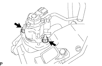
Tighten the oil pipe union (on the head cover side).
Tighten the oil check valve bolt (on the cylinder head side).
| 5. INSTALL NO. 1 OIL PIPE |
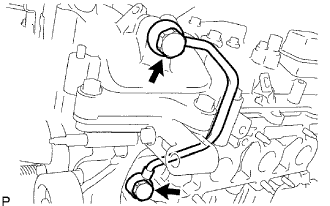 |
Make sure that there is no foreign matter on the mesh of the oil control valve filter LH.
Install the oil control valve filter LH to the oil pipe union. Install new gaskets and temporarily install oil pipe (on the head cover side).
Install a new gasket and temporarily install oil pipe (on the cylinder head side) with the oil check valve bolt.
Tighten the oil pipe union (on the head cover side).
Tighten the oil check valve bolt (on the cylinder head side).
| 6. INSTALL IGNITION COIL ASSEMBLY |
Install the 6 ignition coils with the 6 bolts.
| 7. INSTALL NO. 2 FUEL PIPE SUB-ASSEMBLY |
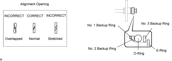
Install a new O-ring, new backup rings (No. 1 and No. 2) and new E-ring to the fuel injector as shown in the illustration.
Apply gasoline to the O-ring and connect the fuel pipe to the delivery pipe.
| 8. INSTALL HIGH PRESSURE SIDE FUEL PUMP |
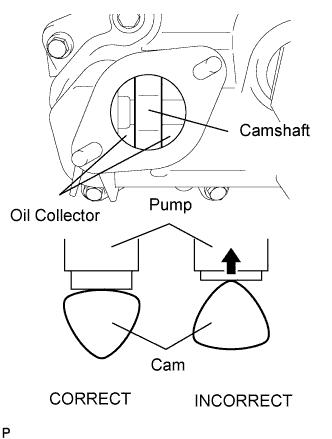 |
Turn the crankshaft until the flat of the cam is facing the cylinder head cover's fuel pump attachment hole, as shown in the illustration.
Pour 30 cc of engine oil through the cylinder head cover's fuel pump attachment hole into the cylinder head oil collector.
 |
Apply a coat of engine oil to the pump activation cam and pump lifter part.
 |
Install a new fuel pump insulator to the cylinder head cover. Then pass the 2 stud bolts through the holes of the fuel pump and set it on the insulator.
Install the union nut of the No. 1 fuel pipe without damaging its seal surface. Tighten the nut as much as possible by hand.
 |
Install the 2 nuts and tighten them in several passes.
Connect the fuel hose.
| 9. INSTALL FUEL MAIN TUBE |
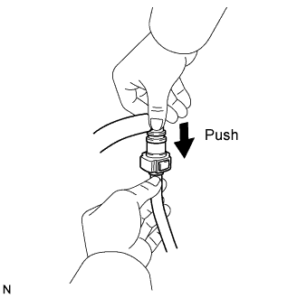 |
Connect the connector to the fuel main pipe. Push the two parts together firmly until a "click" sound is heard. Then attach the lock claws to the connector by pushing down on the connector cover.
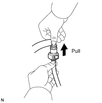 |
Check that the connector and fuel main pipe are securely connected by trying to pull them apart.
 |
Install the fuel pipe clamp.
| 10. INSTALL NO. 1 FUEL PIPE SUB-ASSEMBLY |
 |
Install the No.1 fuel pipe with the 2 bolts.
Connect the fuel pipe hose.
| 11. INSTALL INTAKE AIR SURGE TANK ASSEMBLY |
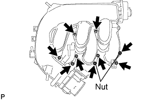 |
Install a new gasket to the intake air surge tank.
Install the intake air surge tank with the 2 nuts.
Using a hexagon socket wrench 5, install the 7 bolts.
Install the 2 surge tank stays with the 4 bolts.
Install the intake manifold stay with the 2 bolts.
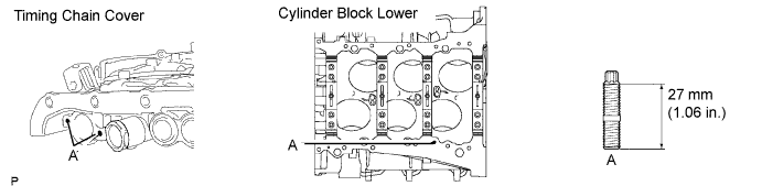
| 12. INSTALL OIL STRAINER SUB-ASSEMBLY |
Using an E6 "torx" socket, install the stud bolts as shown in the illustration.
 |
Install a new gasket and the oil strainer with the 3 nuts.
Install 2 new O-rings.
| 13. INSTALL OIL PAN SUB-ASSEMBLY |
 |
When replacing a stud bolt, install it by using an E6 "torx" socket wrench.
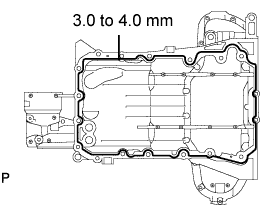 |
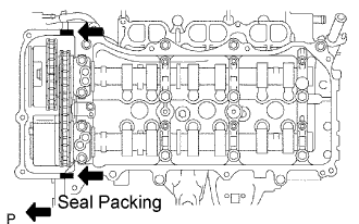
Apply seal packing in a continuous line as shown in the illustration.
 |
Install the oil pan with the 16 bolts and 2 nuts.
| 14. INSTALL NO. 2 OIL PAN SUB-ASSEMBLY |
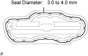 |
Apply seal packing in a continuous line as shown in the illustration.
 |
Install the oil pan with the 15 bolts and 2 nuts.
Install a new gasket and the drain plug.
| 15. INSTALL CRANKSHAFT PULLEY |
 |
Align the pulley set key with the key groove of the pulley, and slide on the pulley.
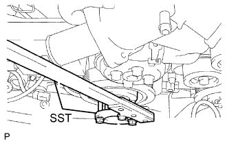
Using SST, install the pulley bolt.
| 16. INSTALL WATER INLET ASSEMBLY |
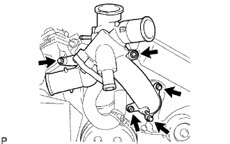 |
Install 2 new O-rings.
Apply soapy water to the O-ring.
Install the water inlet with the 4 bolts and nut.
Install the 3 water by-pass hose.
| 17. INSTALL INJECTOR DRIVER |
 |
Install the injector driver with the bolt and 2 nuts.
| 18. INSTALL WATER PUMP PULLEY |
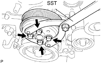 |
Temporarily install the pulley with the 4 bolts.
Using SST, hold the pulley and tighten the 4 bolts.
| 19. INSTALL V-RIBBED BELT TENSIONER ASSEMBLY |
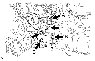 |
Temporarily install the V-ribbed belt tensioner with the 4 bolts.
| Mark | Specified Length |
| A | 70 mm (2.76 in.) |
| B | 33 mm (1.30 in.) |
Tighten bolt 1 shown in the illustration.
Tighten the other bolts.
| 20. INSTALL NO. 2 IDLER PULLEY SUB-ASSEMBLY |
Install the plate and idler pulley with the bolt.
| 21. INSTALL GENERATOR ASSEMBLY |
 |
Install the generator with the 2 bolts.
 |
Install the bracket with the bolt and nut.
 |
Install the battery cable with the nut.
Install the bracket of the wire harness to the generator with the bolt.
Attach the clamp of the wire harness to the generator.
Connect the cable to the generator, and then attach the rubber cap.
| 22. REMOVE ENGINE STAND |
Remove the bolts and engine from the engine stand.
| 23. INSTALL FRONT ENGINE MOUNTING INSULATOR |
Install the mounting bracket with the 4 bolts.
| 24. INSTALL DRIVE PLATE AND RING GEAR SUB-ASSEMBLY |
 |
Using SST, hold the crankshaft.
Apply adhesive to 2 or 3 threads of the mounting bolts end.
Install the front spacer, drive plate and rear spacer on the crankshaft.
 |
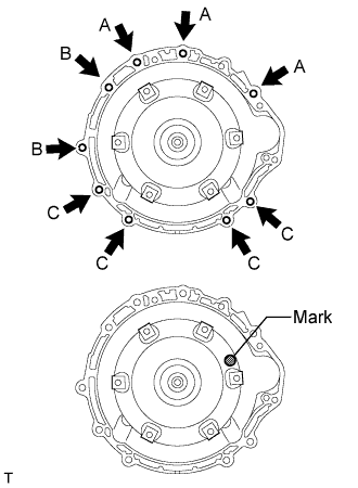
Install and tighten the 8 mounting bolts uniformly in several steps.
| 25. INSTALL AUTOMATIC TRANSMISSION ASSEMBLY |
 |
Install the automatic transmission assembly to the engine with the 9 bolts.
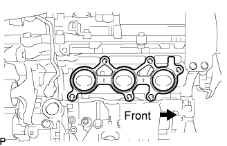
| 26. INSTALL EXHAUST MANIFOLD SUB-ASSEMBLY RH |
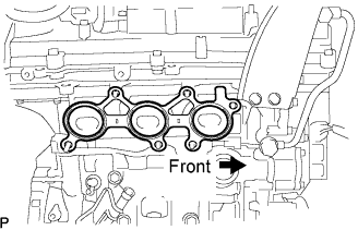 |
Install a new gasket as shown in the illustration.
 |
Install the exhaust manifold with the 6 nuts.
| 27. INSTALL EXHAUST MANIFOLD SUB-ASSEMBLY LH |
 |
Install a new gasket as shown in the illustration.
 |
Install the exhaust manifold with the 6 nuts.
| 28. INSTALL OIL DIPSTICK SUB-ASSEMBLY |
 |
Install a new O-ring to the oil dipstick guide.
Apply a light coat of engine oil to the O-ring.
Push in the oil dipstick guide end into the guide hole.
Install the No. 1 oil dipstick guide with the bolt.
Install the No. 2 oil dipstick guide with the bolt.
Install the oil dipstick.
| 29. INSTALL ENGINE WIRE |
Install the engine wire to the engine assembly.
| 30. INSTALL ENGINE AND TRANSMISSION |
Install the engine and transmission to the vehicle body (Click here).
| 31. ADD ENGINE OIL |
Add new oil.
| Condition | Capacity |
| Drain and refill with oil filter change | 6.3 liters (6.7 US qts, 5.5 imp. qts) |
| Drain and refill without oil filter change | 5.9 liters (6.2 US qts, 5.2 imp. qts) |
| Dry fill | 7.2 liters (7.6 US qts, 6.3 imp. qts) |
Install the oil filter cap.
| 32. ADD AUTOMATIC TRANSMISSION FLUID |
Add the automatic transmission fluid following the flow chart below.

When adding the maximum amount of fluid: [*1]
Lift up the vehicle.
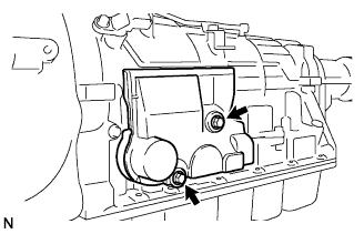 |
Remove the 2 bolts and transmission case cover.
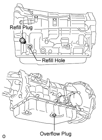 |
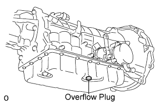
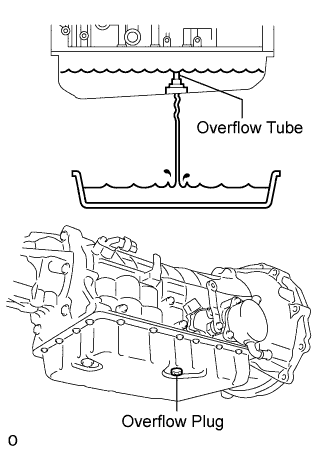
Remove the refill plug and overflow plug.
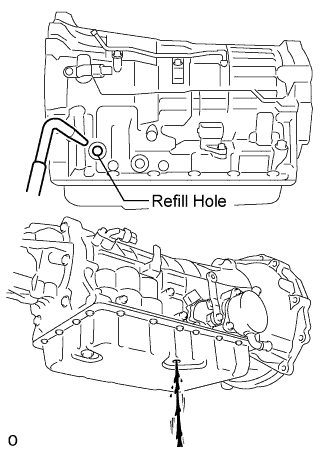 |
Add ATF through the refill hole until it drains out from the overflow hole.
 |
Install a new gasket and the overflow plug.
Add proper amount of ATF through the refill hole.
| Related procedures | Refill amount |
| Removal and installation of oil pan (Including the oil drain) | 1.1 liters (1.2 US qts, 1.0 lmp.qts) |
| Removal of transmission valve body assembly | 2.5 liters (2.6 US qts, 2.2 lmp.qts) |
| Removal of torque converter assembly | 4.2 liters (4.4 US qts, 3.7 lmp.qts) |
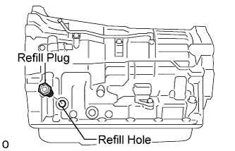 |
Install a new O-ring and the refill plug.
Lower the vehicle.
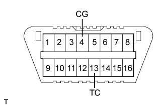 |
Using SST, create a short-circuit between terminals TC and CG of the DLC3.
Start the engine.
Slowly move the shift lever from the P to the S position, shift the gear from 1st to 6th and then return the shift lever to the P position.
Switch to the fluid temperature detection mode.
Return the shift lever to the P position and disconnect terminal TC after confirming the above condition.
Idle the engine to raise fluid temperature.
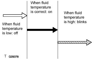 |
Lift up the vehicle immediately after meter indicator light "D" comes on.
|
Remove the overflow plug. If ATF overflows, proceed to [*2].
If ATF does not overflow, proceed to [*3].
 |
When fluid overflows: [*2]
Install a new gasket and the overflow plug when the draining ATF has become a trickle.
Install a new O-ring and tighten the refill plug.
|
Install the transmission case cover with the 2 bolts.
Lower the vehicle.
Turn the engine switch off and remove the SST.
|
When fluid does not overflow:[*3]
Remove the refill plug.
|
Add ATF through the refill hole until it drains out from the overflow hole.
|
Install a new gasket and the overflow plug when the draining ATF has become a trickle.
Install a new O-ring and tighten the refill plug.
|
Install the transmission case cover with the 2 bolts.
Lower the vehicle.
Turn the engine switch off and remove the SST.
|
When adding a minimum amount of fluid: [*4]
Using SST, create a short-circuit between terminals TC and CG of the DLC3.
Start the engine.
Slowly move the shift lever from the P to the S position, shift the gear from 1st to 6th and then return the shift lever to the P position.
Switch to the fluid temperature detection mode.
Return the shift lever to the P position and disconnect terminal TC after confirming the above condition.
Idle the engine to raise fluid temperature.
|
Lift up the vehicle immediately after meter indicator light "D" comes on.
|
Remove the overflow plug. If ATF overflows, proceed to [*5]. If ATF does not overflow, proceed to [*6].
|
When fluid overflows: [*5]
Install a new gasket and the overflow plug when the draining ATF has become a trickle.
|
Install the transmission case cover with the 2 bolts.
Lower the vehicle.
Turn the engine switch off and remove the SST.
|
When fluid does not overflow: [*6]
Remove the refill plug.
|
Add ATF through the refill hole until it drains out from the overflow hole.
|
Install a new gasket and the overflow plug when the draining ATF has become a trickle.
Install a new O-ring and tighten the refill plug.
|
Install the transmission case cover with the 2 bolts.
Lower the vehicle.
Turn the engine switch off and remove the SST.
| 33. ADD ENGINE COOLANT |
Tighten all the plugs and fill the radiator with TOYOTA Super Long Life Coolant (SLLC).
Add engine coolant.
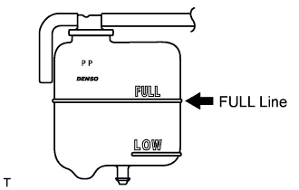
Slowly pour coolant into the radiator reservoir until it reaches the FULL line.
Press the inlet and outlet radiator hoses several times by hand, and then check the level of the coolant.
If the coolant level is low, add coolant.
Install the radiator cap and reservoir cap.
Bleed air from the cooling system.
Warm up the engine until the thermostat opens. While the thermostat is open, circulate the coolant for several minutes.
Maintain the engine speed at 2,000 to 2,500 rpm.
Press the inlet and outlet radiator hoses several times by hand to bleed air.
Stop the engine, and wait until the engine coolant cools down to ambient temperature.
 |
Check the coolant level in the radiator reservoir.
If the coolant level is low, add SLLC to the radiator reservoir FULL line.
| 34. CONNECT CABLE TO NEGATIVE BATTERY TERMINAL |
| 35. PERFORM INITIALIZATION |
Perform initialization (Click here).
| 36. CHECK SHIFT LEVER POSITION |
When shifting from the P to the R position with the engine switch on (IG) and brake pedal depressed, make sure that the shift lever moves smoothly and moves correctly into position.
Start the engine and make sure that the vehicle moves forward when shifting from the N to the D position and moves rearward when shifting to the R position.
If operation cannot be done as specified, inspect the park/neutral position switch assembly and check the shift lever assembly installation condition.
| 37. CHECK AND ADJUST FRONT WHEEL ALIGNMENT |
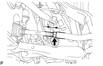
Measure the thread lengths of the right and left rack ends.
Remove the rack boot set clips.
Loosen the tie rod end lock nuts.
Adjust the rack ends if the difference in thread length between the right and left rack ends is not within the specified range.
Extend the shorter rack end if the measured toe-in deviates toward the outer-side.
Shorten the longer rack end if the measured toe-in deviates toward the inner-side.
Turn the right and left rack ends by an equal amount to adjust toe-in.
 |
Make sure that the lengths of the right and left rack ends are the same.
Tighten the tie rod end lock nuts.
Place the boots on the seats and install the clips.
| 38. CHECK IGNITION TIMING |
Warm up the engine and stop the engine.
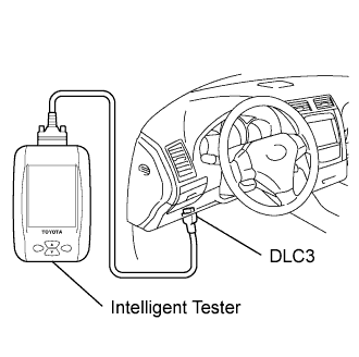 |
When using the intelligent tester:
Connect the intelligent tester to the DLC3.
Start the engine and idle it.
Push the intelligent tester main switch ON.
Enter the following items: Powertrain / Engine and ECT / Data list / IGN Advance.
When not using the intelligent tester:
Remove the V-bank cover.
 |
Connect the tester probe of a timing light to the wire of the ignition connector for the No. 1 cylinder.
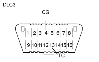 |
Using SST, connect the terminals TC and CG of the DLC3.
 |
Using a timing light, check the ignition timing.
Remove the SST from the DLC3.
Check the ignition timing.
Check that the ignition timing advances immediately when the engine speed is increased.
Disconnect the timing light from the engine.
Install the V-bank cover.
| 39. CHECK IDLE SPEED |
Warm up and stop the engine.
|
When using the intelligent tester:
Connect the intelligent tester to the DLC3.
Race the engine speed at 2,500 rpm for approximately 90 seconds.
Push the intelligent tester main switch ON.
Enter the following items: Powertrain / Engine and ECT / Data list / Engine SPD.
Disconnect the intelligent tester from the DLC3.
 |
When not using the intelligent tester:
Using SST, connect the tachometer probe to terminal TAC of the DLC3.
Race the engine speed at 2,500 rpm for approximately 90 seconds.
Check the idle speed.
Disconnect the tachometer from the DLC3.
| 40. CHECK CO/HC |
Start the engine.
Keep the engine speed at 2,500 rpm for approximately 180 seconds.
 |
Insert CO / HC meter testing probe at least 40 cm (1.3 ft.) into tailpipe during idling.
Immediately check CO / HC concentration at idle and / or 2,500 rpm.
Check the A/F sensor and heated oxygen sensor operation.
See the table below for possible cause, then inspect and correct the applicable causes if necessary.
| CO | HC | Symptom | Causes |
| Normal | High | Rough idle |
|
| Low | High | Rough idle (Fluctuating HC reading) |
|
| High | High | Rough idle (Black smoke from exhaust) |
|
| 41. CHECK FOR ENGINE OIL LEAKS |
| 42. CHECK FOR ENGINE COOLANT LEAKS |
| 43. CHECK FOR FUEL LEAKS |
| 44. CHECK ENGINE OIL LEVEL |
| 45. CHECK AUTOMATIC TRANSMISSION FLUID LEVEL |
| 46. CHECK ENGINE COOLANT LEVEL |
