OIL PUMP > REMOVAL |
| 1. DISCHARGE FUEL SYSTEM PRESSURE |
Disconnect the cable from the negative (-) battery terminal.
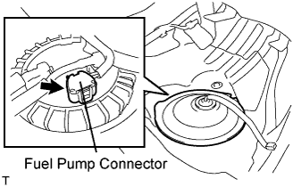 |
Disconnect the fuel pump connector.
Connect the cable to the negative (-) battery terminal.
Start the engine. After the engine has stopped on its own, turn the engine switch off.
Crank the engine again, then check that the engine does not start.
Loosen the fuel tank cap, then discharge the pressure in the fuel tank completely.
Connect the fuel pump connector.
| 2. DISCONNECT CABLE FROM NEGATIVE BATTERY TERMINAL |
| 3. DRAIN ENGINE OIL |
Remove the drain plug.
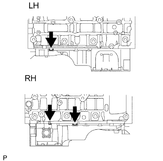
| 4. DRAIN ENGINE COOLANT |
Remove the radiator cap and reservoir cap.
Loosen the radiator drain cock plug and 2 cylinder block drain cock plugs. Then drain the coolant.

| 5. DRAIN AUTOMATIC TRANSMISSION FLUID |
Add the automatic transmission fluid following the flow chart below.

When adding the maximum amount of fluid: [*1]
Lift up the vehicle.
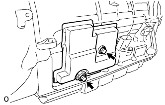 |
Remove the 2 bolts and transmission case cover.
 |
Remove the refill plug and overflow plug.
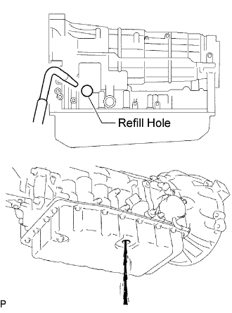 |
Add ATF through the refill hole until it drains out from the overflow hole.
 |
Install a new gasket and the overflow plug.
Add proper amount of ATF through the refill hole.
| Related procedures | Refill amount |
| Removal and installation of oil pan (Including the oil drain) | 1.3 liters (1.4 US qts, 1.1 lmp.qts) |
| Removal of transmission valve body assembly | 3.3 liters (3.5 US qts, 2.9 lmp.qts) |
| Removal of torque converter assembly | 4.4 liters (4.7 US qts, 3.9 lmp.qts) |
 |
Install a new O-ring and the refill plug.
Lower the vehicle.
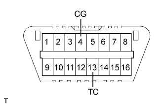 |
Using SST, create a short-circuit between terminals TC and CG of the DLC3.
Start the engine.
Slowly move the shift lever from the P to the S position, shift the gear from 1st to 6th and then return the shift lever to the P position.
Switch to the fluid temperature detection mode.
Return the shift lever to the P position and disconnect terminal TC after confirming the above condition.
Idle the engine to raise fluid temperature.
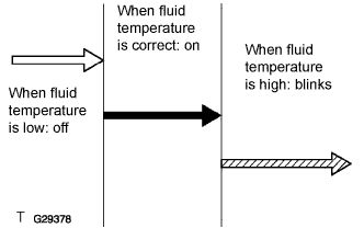 |
Lift up the vehicle immediately after meter indicator light "D" comes on.
|
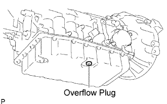
Remove the overflow plug. If ATF overflows, proceed to [*2].
If ATF does not overflow, proceed to [*3].
 |
When fluid overflows: [*2]
Install a new gasket and the overflow plug when the draining ATF has become a trickle.
Install a new O-ring and tighten the refill plug.
|
Install the transmission case cover with the 2 bolts.
Lower the vehicle.
Turn the engine switch off and remove the SST.
When fluid does not overflow:[*3]
|
Remove the refill plug.
|
Add ATF through the refill hole until it drains out from the overflow hole.
|
Install a new gasket and the overflow plug when the draining ATF has become a trickle.
Install a new O-ring and tighten the refill plug.
|
Install the transmission case cover with the 2 bolts.
Lower the vehicle.
Turn the engine switch off and remove the SST.
When adding a minimum amount of fluid: [*4]
|
Using SST, create a short-circuit between terminals TC and CG of the DLC3.
Start the engine.
Slowly move the shift lever from the P to the S position, shift the gear from 1st to 6th and then return the shift lever to the P position.
Switch to the fluid temperature detection mode.
Return the shift lever to the P position and disconnect terminal TC after confirming the above condition.
Idle the engine to raise fluid temperature.
|
Lift up the vehicle immediately after meter indicator light "D" comes on.
|
Remove the overflow plug. If ATF overflows, proceed to [*5]. If ATF does not overflow, proceed to [*6].
When fluid overflows: [*5]
|
Install a new gasket and the overflow plug when the draining ATF has become a trickle.
|
Install the transmission case cover with the 2 bolts.
Lower the vehicle.
Turn the engine switch off and remove the SST.
When fluid does not overflow: [*6]
|
Remove the refill plug.
|
Add ATF through the refill hole until it drains out from the overflow hole.
|
Install a new gasket and the overflow plug when the draining ATF has become a trickle.
Install a new O-ring and tighten the refill plug.
|
Install the transmission case cover with the 2 bolts.
Lower the vehicle.
Turn the engine switch off and remove the SST.
| 6. REMOVE ENGINE AND TRANSMISSION ASSEMBLY |
Remove the engine and transmission assembly (Click here).
| 7. REMOVE ENGINE WIRE |
Remove the engine wire.
| 8. REMOVE OIL DIPSTICK SUB-ASSEMBLY |
 |
Remove the oil dipstick.
Remove the 2 bolts, then remove the No. 1 and No. 2 oil dipstick guide.
Remove the O-ring from the oil level gauge guide.
| 9. REMOVE EXHAUST MANIFOLD SUB-ASSEMBLY RH |
Disconnect the heated oxygen sensor connector.
Remove the 6 nuts, exhaust manifold and gasket.
| 10. REMOVE EXHAUST MANIFOLD SUB-ASSEMBLY LH |
Disconnect the heated oxygen sensor connector.
Remove the 6 nuts, exhaust manifold and gasket.
| 11. REMOVE AUTOMATIC TRANSMISSION ASSEMBLY |
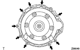 |
Remove the 9 bolts and automatic transmission assembly.
| 12. REMOVE DRIVE PLATE AND RING GEAR SUB-ASSEMBLY |
 |
Using SST, hold the crankshaft.
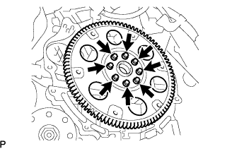 |
Remove the 8 bolts, front spacer, drive plate and rear spacer.
| 13. REMOVE FRONT ENGINE MOUNTING INSULATOR |
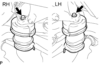 |
Remove the 2 bolts, then remove the front suspension crossmember sub-assembly from the engine.
| 14. FIX ENGINE ONTO ENGINE STAND |
Fix the engine onto a engine stand with the bolts.
| 15. REMOVE GENERATOR ASSEMBLY |
 |
Detach the clamp, and remove the bolt from the generator.
Disconnect the generator connector.
Detach the rubber cap, and then remove the nut and battery cable.
 |
Remove the nut, bolt and generator bracket.
 |
Remove the 2 bolts and generator.
| 16. REMOVE NO. 2 IDLER PULLEY SUB-ASSEMBLY |
Remove the bolt, plate and idler pulley.
| 17. REMOVE V-RIBBED BELT TENSIONER ASSEMBLY |
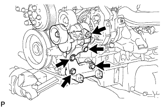 |
Remove the 5 bolts, then remove the V-ribbed belt tensioner assembly.
| 18. REMOVE WATER PUMP PULLEY |
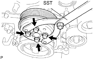 |
Using SST, hold the water pump pulley.
Remove the 4 bolts and water pump pulley.
| 19. REMOVE WATER INLET ASSEMBLY |
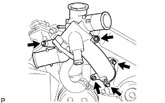 |
Remove the 3 water by-pass hoses.
Remove the 4 bolts, nut and water inlet.
Remove the O-rings.
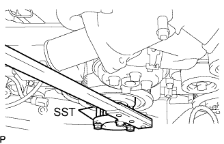
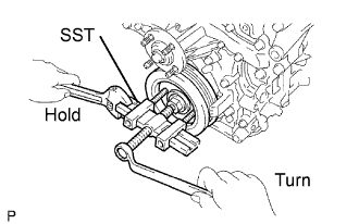
| 20. REMOVE CRANKSHAFT PULLEY |
 |
Using SST, loosen the crankshaft pulley bolt.
 |
Using SST, remove the crankshaft pulley bolt and crankshaft pulley.
| 21. REMOVE NO. 2 OIL PAN SUB-ASSEMBLY |
 |
Remove the 15 bolts and 2 nuts.
Insert the blade of SST between the oil pans. Cut through the applied sealer and remove the oil pan sub-assembly No. 2.
| 22. REMOVE OIL PAN SUB-ASSEMBLY |
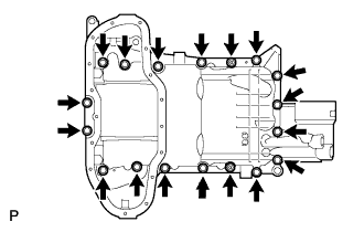 |
Remove the 16 bolts and 2 nuts.
 |
Remove the oil pan by prying between the oil pan and cylinder block with a screwdriver.
Remove the 2 O-rings.
| 23. REMOVE OIL STRAINER SUB-ASSEMBLY |
 |
Remove the 3 nuts, oil strainer and gasket.
| 24. REMOVE INTAKE AIR SURGE TANK ASSEMBLY |
Remove the 2 bolts and intake manifold stay.
Remove the 4 bolts and 2 surge tank stays.
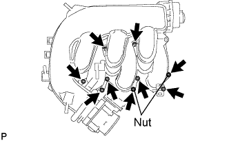 |
Using a 5 mm hexagon socket wrench, remove the 7 bolts, 2 nuts and gasket.
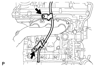
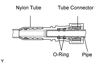
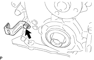
| 25. REMOVE FUEL MAIN TUBE |
 |
Remove the fuel pipe clamp.
 |
Pinch and pull the fuel hose's connector to disconnect it from the fuel pipe.
 |
 |
| 26. REMOVE IGNITION COIL ASSEMBLY |
Remove the 6 bolts and 6 ignition coils.
| 27. REMOVE NO. 1 OIL PIPE |
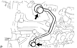 |
Remove the oil check valve bolt, oil pipe union and oil pipe.
Remove the oil control valve filter LH and gaskets.
| 28. REMOVE NO. 2 OIL PIPE |
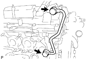 |
Remove the oil check valve bolt, oil pipe union and oil pipe.
Remove the oil control valve filter RH and gaskets.
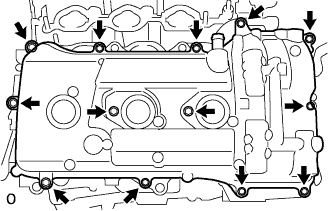
| 29. REMOVE CYLINDER HEAD COVER SUB-ASSEMBLY RH (for Bank 1) |
 |
Remove the 13 bolts, head cover and gasket.
| 30. REMOVE CYLINDER HEAD COVER SUB-ASSEMBLY LH (for Bank 2) |
 |
Remove the 12 bolts, head cover and gasket.
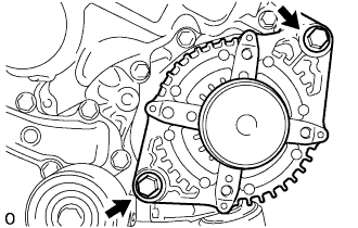
| 31. REMOVE TIMING CHAIN OR BELT COVER SUB-ASSEMBLY |
 |
Remove the bolt and wiring harness clamp bracket.
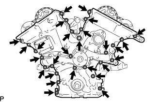 |
Remove the 25 bolts and 2 nuts shown in the illustration.
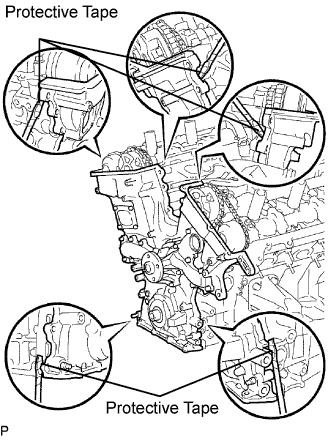 |
Remove the timing chain cover by prying between the timing chain cover and cylinder head or cylinder block with a screwdriver.
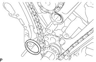 |
Remove the gasket.
