FRONT POWER SEAT CONTROL SYSTEM (w/ Seat Position Memory System) > TERMINALS OF ECU |
| INSPECT POSITION CONTROL ECU & SWITCH ASSEMBLY LH |

Disconnect the d7 and d8 ECU connectors.
Measure the voltage and resistance of the wire harness side connectors.
| Symbols (Terminal No.) | Wiring Color | Terminal Description | Condition | Specified Condition |
| IG (d7-4) - GND (d8-1) | B - W-B | Engine switch signal | Engine switch off | Below 1 V |
| IG (d7-4) - GND (d8-1) | B - W-B | Engine switch signal | Engine switch on (IG) | 10 to 14 V |
| +B (d8-5) - GND (d8-1) | L - W-B | Power source | Always | 10 to 14 V |
| SYSB (d7-8) - GND (d8-1) | G - W-B | System power source | Always | 10 to 14 V |
| GND (d8-1) - Body ground | W-B - Body ground | Ground | Always | Below 1 Ω |
Reconnect the d7 and d8 ECU connectors.
Measure the voltage of the connector.
| Symbols (Terminal No.) | Wiring Color | Terminal Description | Condition | Specified Condition |
| SLD+ (d8-2) - GND (d8-1) | B - W-B | Sliding motor signal (forward) | Slide switch OFF | Below 1 V |
| SLD+ (d8-2) - GND (d8-1) | B - W-B | Sliding motor signal (forward) | Slide switch FRONT ON | 10 to 14 V |
| SLD- (d8-3) - GND (d8-1) | G - W-B | Sliding motor signal (rearward) | Slide switch OFF | Below 1 V |
| SLD- (d8-3) - GND (d8-1) | G - W-B | Sliding motor signal (rearward) | Slide switch REAR ON | 10 to 14 V |
| FRV+ (d8-6) - GND (d8-1) | W - W-B | Front vertical motor signal (upward) | Front vertical switch OFF | Below 1 V |
| FRV+ (d8-6) - GND (d8-1) | W - W-B | Front vertical motor signal (upward) | Front vertical switch UP ON | 10 to 14 V |
| FRV- (d8-4) - GND (d8-1) | R - W-B | Front vertical motor signal (downward) | Front vertical switch OFF | Below 1 V |
| FRV- (d8-4) - GND (d8-1) | R - W-B | Front vertical motor signal (downward) | Front vertical switch DOWN ON | 10 to 14 V |
| LFT+ (d8-7) - GND (d8-1) | Y - W-B | Lifter motor signal (upward) | Lifter switch OFF | Below 1 V |
| LFT+ (d8-7) - GND (d8-1) | Y - W-B | Lifter motor signal (upward) | Lifter switch UP ON | 10 to 14 V |
| LFT- (d8-9) - GND (d8-1) | LG - W-B | Lifter motor signal (downward) | Lifter switch OFF | Below 1 V |
| LFT- (d8-9) - GND (d8-1) | LG - W-B | Lifter motor signal (downward) | Lifter switch DOWN ON | 10 to 14 V |
| RCL+ (d8-8) - GND (d8-1) | L - W-B | Reclining motor signal (forward) | Reclining switch OFF | Below 1 V |
| RCL+ (d8-8) - GND (d8-1) | L - W-B | Reclining motor signal (forward) | Reclining switch FRONT ON | 10 to 14 V |
| RCL- (d8-10) - GND (d8-1) | GR - W-B | Reclining motor signal (rearward) | Reclining switch OFF | Below 1 V |
| RCL- (d8-10) - GND (d8-1) | GR - W-B | Reclining motor signal (rearward) | Reclining switch REAR ON | 10 to 14 V |
| INSPECT POSITION CONTROL ECU & SWITCH ASSEMBLY RH |

Disconnect the c6 and c7 ECU connectors.
Measure the voltage and resistance of the wire harness side connectors.
| Symbols (Terminal No.) | Wiring Color | Terminal Description | Condition | Specified Condition |
| IG (c7-4) - GND (c6-1) | B - W-B | Engine switch signal | Engine switch off | Below 1 V |
| IG (c7-4) - GND (c6-1) | B - W-B | Engine switch signal | Engine switch on (IG) | 10 to 14 V |
| +B (c6-5) - GND (c6-1) | L - W-B | Power source | Always | 10 to 14 V |
| SYSB (c7-8) - GND (c6-1) | R - W-B | System power source | Always | 10 to 14 V |
| GND (c6-1) - Body ground | W-B - Body ground | Ground | Always | Below 1 Ω |
Reconnect the c6 and c7 ECU connectors.
Measure the voltage of the connector.
| Symbols (Terminal No.) | Wiring Color | Terminal Description | Condition | Specified Condition |
| SLD+ (c6-2) - GND (c6-1) | B - W-B | Sliding motor signal (forward) | Slide switch OFF | Below 1 V |
| SLD+ (c6-2) - GND (c6-1) | B - W-B | Sliding motor signal (forward) | Slide switch FRONT ON | 10 to 14 V |
| SLD- (c6-3) - GND (c6-1) | G - W-B | Sliding motor signal (rearward) | Slide switch OFF | Below 1 V |
| SLD- (c6-3) - GND (c6-1) | G - W-B | Sliding motor signal (rearward) | Slide switch REAR ON | 10 to 14 V |
| FRV+ (c6-6) - GND (c6-1) | W - W-B | Front vertical motor signal (upward) | Front vertical switch OFF | Below 1 V |
| FRV+ (c6-6) - GND (c6-1) | W - W-B | Front vertical motor signal (upward) | Front vertical switch UP ON | 10 to 14 V |
| FRV- (c6-4) - GND (c6-1) | R - W-B | Front vertical motor signal (downward) | Front vertical switch OFF | Below 1 V |
| FRV- (c6-4) - GND (c6-1) | R - W-B | Front vertical motor signal (downward) | Front vertical switch DOWN ON | 10 to 14 V |
| LFT+ (c6-7) - GND (c6-1) | Y - W-B | Lifter motor signal (upward) | Lifter switch OFF | Below 1 V |
| LFT+ (c6-7) - GND (c6-1) | Y - W-B | Lifter motor signal (upward) | Lifter switch UP ON | 10 to 14 V |
| LFT- (c6-9) - GND (c6-1) | LG - W-B | Lifter motor signal (downward) | Lifter switch OFF | Below 1 V |
| LFT- (c6-9) - GND (c6-1) | LG - W-B | Lifter motor signal (downward) | Lifter switch DOWN ON | 10 to 14 V |
| RCL+ (c6-8) - GND (c6-1) | L - W-B | Reclining motor signal (forward) | Reclining switch OFF | Below 1 V |
| RCL+ (c6-8) - GND (c6-1) | L - W-B | Reclining motor signal (forward) | Reclining switch FRONT ON | 10 to 14 V |
| RCL- (c6-10) - GND (c6-1) | GR - W-B | Reclining motor signal (rearward) | Reclining switch OFF | Below 1 V |
| RCL- (c6-10) - GND (c6-1) | GR - W-B | Reclining motor signal (rearward) | Reclining switch REAR ON | 10 to 14 V |
| INSPECT MULTIPLEX NETWORK MASTER SWITCH ASSEMBLY |
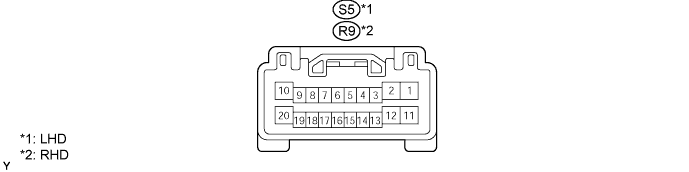
Disconnect the S5 or R9 master switch connector.
Measure the voltage and resistance of the wire harness side connector.
| Symbols (Terminal No.) | Wiring Color | Terminal Description | Condition | Specified Condition |
| E (S5-2) - Body ground | W-B - Body ground | Ground | Always | Below 1 Ω |
| BDR1 (S5-10) - E (S5-2) | Y - W-B | Power window power source | Always | 10 to 14 V |
| CPUB (S5-9) - E (S5-2) | G - W-B | Power source for CPU and relevant device | Always | 10 to 14 V |
| SIG (S5-20) - E (S5-2) | V - W-B | Power source for CPU and relevant device | Engine switch off | Below 1 V |
| SIG (S5-20) - E (S5-2) | V - W-B | Power source for CPU and relevant device | Engine switch on (IG) | 10 to 14 V |
| Symbols (Terminal No.) | Wiring Color | Terminal Description | Condition | Specified Condition |
| E (R9-2) - Body ground | W-B - Body ground | Ground | Always | Below 1 Ω |
| BDR1 (R9-10) - E (R9-2) | Y - W-B | Power window power source | Always | 10 to 14 V |
| CPUB (R9-9) - E (R9-2) | G - W-B | Power source for CPU and relevant device | Always | 10 to 14 V |
| SIG (R9-20) - E (R9-2) | V - W-B | Power source for CPU and relevant device | Engine switch off | Below 1 V |
| SIG (R9-20) - E (R9-2) | V - W-B | Power source for CPU and relevant device | Engine switch on (IG) | 10 to 14 V |
Reconnect the S5 or R9 master switch connector.
Measure the voltage of the connector.
| Symbols (Terminal No.) | Wiring Color | Terminal Description | Condition | Specified Condition |
| MM (S5-3) - E (S5-2) | SB - W-B | SET switch signal | SET switch OFF | 10 to 14 V |
| MM (S5-3) - E (S5-2) | SB - W-B | SET switch signal | SET switch ON | Below 1 V |
| M1 (S5-13) - E (S5-2) | L - W-B | M1 switch signal | M1 switch OFF | 10 to 14 V |
| M1 (S5-13) - E (S5-2) | L - W-B | M1 switch signal | M1 switch ON | Below 1 V |
| M2 (S5-17) - E (S5-2) | V - W-B | M2 switch signal | M2 switch OFF | 10 to 14 V |
| M2 (S5-17) - E (S5-2) | V - W-B | M2 switch signal | M2 switch ON | Below 1 V |
| M3 (S5-18) - E (S5-2) | R - W-B | M3 switch signal | M3 switch OFF | 10 to 14 V |
| M3 (S5-18) - E (S5-2) | R - W-B | M3 switch signal | M3 switch ON | Below 1 V |
| Symbols (Terminal No.) | Wiring Color | Terminal Description | Condition | Specified Condition |
| MM (R9-3) - E (R9-2) | Y - W-B | SET switch signal | SET switch OFF | 10 to 14 V |
| MM (R9-3) - E (R9-2) | Y - W-B | SET switch signal | SET switch ON | Below 1 V |
| M1 (R9-13) - E (R9-2) | O - W-B | M1 switch signal | M1 switch OFF | 10 to 14 V |
| M1 (R9-13) - E (R9-2) | O - W-B | M1 switch signal | M1 switch ON | Below 1 V |
| M2 (R9-17) - E (R9-2) | LG - W-B | M2 switch signal | M2 switch OFF | 10 to 14 V |
| M2 (R9-17) - E (R9-2) | LG - W-B | M2 switch signal | M2 switch ON | Below 1 V |
| M3 (R9-18) - E (R9-2) | SB - W-B | M3 switch signal | M3 switch OFF | 10 to 14 V |
| M3 (R9-18) - E (R9-2) | SB - W-B | M3 switch signal | M3 switch ON | Below 1 V |
| CHECK FRONT MULTIPLEX NETWORK DOOR ECU LH |
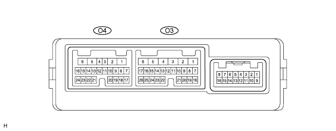
Disconnect the O3 and O4 ECU connectors.
Measure the voltage and resistance of the wire harness side connector.
| Symbols (Terminal No.) | Wiring Color | Terminal Description | Condition | Specified Condition |
| GND (O3-1) - Body ground | W-B - Body ground | Ground | Always | Below 1 Ω |
| CPUB (O3-4) - GND (O3-1) | LG - W-B | Battery (ECU power source) | Always | 10 to 14 V |
| SIG (O3-3) - GND (O3-1) | Y - W-B | Engine switch (IG) power supply | Engine switch off | Below 1 V |
| SIG (O3-3) - GND (O3-1) | Y - W-B | Engine switch (IG) power supply | Engine switch on (IG) | 10 to 14 V |
| BDR (O3-6) - GND (O3-1) | L - W-B | Battery (ECU power source) | Always | 10 to 14 V |
| *SEL1 (O4-11) - SELE (O4-12) | P - P | Terminal for identification of driver side | Always | Below 1 Ω |
Reconnect the O3 and O4 ECU connectors.
Measure the voltage of the connectors.
| Symbols (Terminal No.) | Wiring Color | Terminal Description | Condition | Specified Condition |
| MSWE (O3-26) - GND (O3-1) | W-B - W-B | Ground for seat memory switch | Always | Below 1 V |
| SEL1 (O4-11) - GND (O3-1) | P - W-B | Terminal for identification of driver side | Always | Below 1 V |
| Symbols (Terminal No.) | Wiring Color | Terminal Description | Condition | Specified Condition |
| MSWE (O3-26) - GND (O3-1) | W-B - W-B | Ground for seat memory switch | Always | Below 1 V |
| MM (O3-25) - MSWE (O3-26) | Y - W-B | SET switch signal | SET switch OFF | 10 to 14 V |
| MM (O3-25) - MSWE (O3-26) | Y - W-B | SET switch signal | SET switch ON | Below 1 V |
| M1 (O3-22) - MSWE (O3-26) | O - W-B | M1 switch signal | M1 switch OFF | 10 to 14 V |
| M1 (O3-22) - MSWE (O3-26) | O - W-B | M1 switch signal | M1 switch ON | Below 1 V |
| M2 (O3-23) - MSWE (O3-26) | LG - W-B | M2 switch signal | M2 switch OFF | 10 to 14 V |
| M2 (O3-23) - MSWE (O3-26) | LG - W-B | M2 switch signal | M2 switch ON | Below 1 V |
| M3 (O3-24) - MSWE (O3-26) | SB - W-B | M3 switch signal | M3 switch OFF | 10 to 14 V |
| M3 (O3-24) - MSWE (O3-26) | SB - W-B | M3 switch signal | M3 switch ON | Below 1 V |
| CHECK FRONT MULTIPLEX NETWORK DOOR ECU RH |
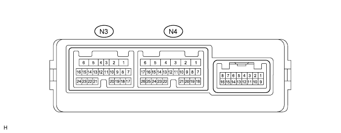
Disconnect the N3 and N4 ECU connectors.
Measure the voltage and resistance of the wire harness side connectors.
| Symbols (Terminal No.) | Wiring Color | Terminal Description | Condition | Specified Condition |
| GND (N4-1) - Body ground | W-B - Body ground | Ground | Always | Below 1 Ω |
| CPUB (N4-4) - GND (N4-1) | L-G - W-B | Battery (ECU power source) | Always | 10 to 14 V |
| SIG (N4-3) - GND (N4-1) | L - W-B | Engine switch (IG) power supply | Engine switch off | Below 1 V |
| SIG (N4-3) - GND (N4-1) | L - W-B | Engine switch (IG) power supply | Engine switch on (IG) | 10 to 14 V |
| BDR (N4-6) - GND (N4-1) | L - W-B | Battery (ECU power source) | Always | 10 to 14 V |
| *SEL1 (N3-11) - SELE (N3-12) | P - P | Terminal for identification of driver side | Always | Below 1 Ω |
Reconnect the N3 and N4 ECU connectors.
Measure the voltage of the connectors.
| Symbols (Terminal No.) | Wiring Color | Terminal Description | Condition | Specified Condition |
| MSWE (N4-26) - GND (N4-1) | W-B - W-B | Ground for seat memory switch | Always | Below 1 V |
| MM (N4-25) - MSWE (N4-26) | Y - W-B | SET switch signal | SET switch OFF | 10 to 14 V |
| MM (N4-25) - MSWE (N4-26) | Y - W-B | SET switch signal | SET switch ON | Below 1 V |
| M1 (N4-22) - MSWE (N4-26) | O - W-B | M1 switch signal | M1 switch OFF | 10 to 14 V |
| M1 (N4-22) - MSWE (N4-26) | O - W-B | M1 switch signal | M1 switch ON | Below 1 V |
| M2 (N4-23) - MSWE (N4-26) | LG - W-B | M2 switch signal | M2 switch OFF | 10 to 14 V |
| M2 (N4-23) - MSWE (N4-26) | LG - W-B | M2 switch signal | M2 switch ON | Below 1 V |
| M3 (N4-24) - MSWE (N4-26) | SB - W-B | M3 switch signal | M3 switch OFF | 10 to 14 V |
| M3 (N4-24) - MSWE (N4-26) | SB - W-B | M3 switch signal | M3 switch ON | Below 1 V |
| Symbols (Terminal No.) | Wiring Color | Terminal Description | Condition | Specified Condition |
| MSWE (N4-26) - GND (N4-1) | W-B - W-B | Ground for seat memory switch | Always | Below 1 V |
| SEL1 (N3-11) - GND (N3-1) | P - W-B | Terminal for identification of driver side | Always | Below 1 V |
