DTC    P0617    Starter Relay Circuit High

for Preparation Click here


DESCRIPTION

While the engine is being cranked, the positive (+) battery voltage is applied to terminal STA of the ECM.
If the ECM detects the Starter Control (STA) signal while the vehicle is being driven, it determines that there is a malfunction in the STA circuit. The ECM then illuminates the MIL and sets the DTC.
This monitor runs when the vehicle is driven at 12.4 mph (20 km/h) for 20 seconds or more.

DTC No.
DTC Detection Condition
Trouble Area
P0617
The following conditions are met for 20 seconds:
  1. Vehicle speed is greater than 20 km/h (12 mph)
  2. Engine RPM is greater than 1,000 rpm
  3. ECM detects STA
  1. Short in Park/Neutral Position (PNP) switch circuit
  2. PNP switch
  3. Engine switch
  4. ECM

WIRING DIAGRAM


A105235E03


A105234E03


INSPECTION PROCEDURE

HINT:
  1. The following troubleshooting flowchart is based on the premise that the engine is cranked normally.
    If the engine will not crank, proceed to the problem symptoms table (Click here).
  2. Read freeze frame data using the intelligent tester. Freeze frame data records the engine conditions when a malfunction is detected. When troubleshooting, freeze frame data can help determine if the vehicle was moving or stationary, if the engine was warmed up or not, if the air-fuel ratio was LEAN or RICH, and other data from the time the malfunction occurred.

1.READ DATA LIST (STARTER SIGNAL)
  1. Connect the intelligent tester to the DLC3.

  1. Turn the engine switch on (IG) and turn the tester ON.

  1. Enter the following menus: Powertrain / Engine / Data List / Primary / Starter Signal.

  1. Confirm the starter signal status when the engine switch is operated.

    OK:

    Engine Switch Position
    Starter Signal
    On (IG)
    OFF
    Start
    ON


OK
REPLACE ECM
NG


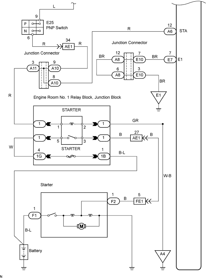
2.INSPECT PARK / NEUTRAL POSITION SWITCH
G027076
  1. Move the shift lever to the P or N position.

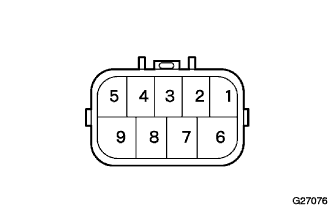
  1. Disconnect the E25 PNP switch connector.

  1. Measure the resistance of the PNP switch.

    Standard resistance:
    Shift Position
    Tester Connection
    Specified Condition
    P or N
    E25-9 - E25-6
    Below 1 Ω


NG
REPLACE PARK / NEUTRAL POSITION SWITCH (THEN CHECK CRANKING HOLDING FUNCTION)
OK

CHECK CRANKING HOLDING FUNCTION CIRCUIT