DTC P0351 Ignition Coil "A" Primary / Secondary Circuit |
DTC P0352 Ignition Coil "B" Primary / Secondary Circuit |
DTC P0353 Ignition Coil "C" Primary / Secondary Circuit |
DTC P0354 Ignition Coil "D" Primary / Secondary Circuit |
DTC P0355 Ignition Coil "E" Primary / Secondary Circuit |
DTC P0356 Ignition Coil "F" Primary / Secondary Circuit |
DTC P0357 Ignition Coil "G" Primary / Secondary Circuit |
DTC P0358 Ignition Coil "H" Primary / Secondary Circuit |
| DTC No. | DTC Detection Condition | Trouble Area |
| P0351 P0352 P0353 P0354 P0355 P0356 P0357 P0358 | No IGF signal to ECM while engine is running (1 trip detection logic) |
|


| 1.INSPECT SPARK PLUG |
 |
Remove the engine cover.
Remove the ignition coil and the spark plug of the misfiring cylinder.
Check the electrode for carbon deposits.
Measure the spark plug's electrode gap.
| Manufacturer | Spark Plug Type |
| DENSO | SK20R11 |
| NGK | IFR6A11 |
|
| ||||
| OK | |
| 2.CHECK SPARK AND IGNITION |
 |
Disconnect the injector connectors to prevent the engine from starting.
Install the spark plug to the ignition coil.
Attach the spark plug to the cylinder head cover.
Crank the engine within 2 seconds and check the spark.
|
| ||||
| OK | |
| 3.CHECK WIRE HARNESS (IGNITION COIL - ECM) |
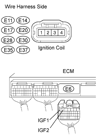 |
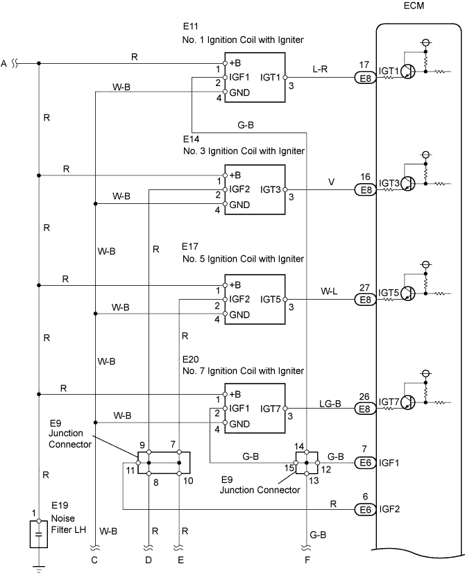
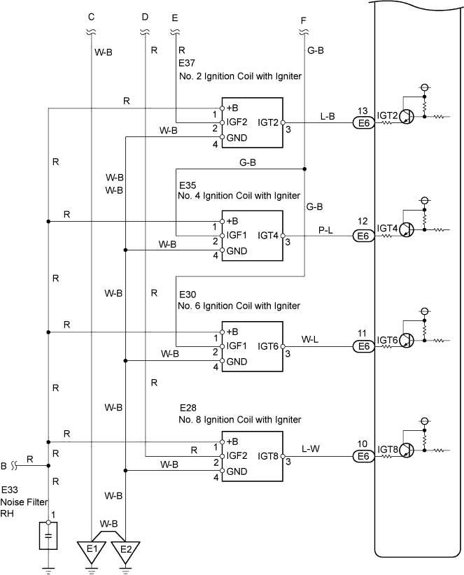
Disconnect the E11, E14, E17, E20, E28, E30, E35 and E37 ignition coil connectors.
Disconnect the E6 ECM connector.
Measure the resistance of the wire harness side connectors.
| Tester Connection | Specified Condition |
| E11-2 (IGF1) - E6-7 (IGF1) | Below 1 Ω |
| E37-2 (IGF2) - E6-6 (IGF2) | Below 1 Ω |
| E14-2 (IGF2) - E6-6 (IGF2) | Below 1 Ω |
| E35-2 (IGF1) - E6-7 (IGF1) | Below 1 Ω |
| E17-2 (IGF2) - E6-6 (IGF2) | Below 1 Ω |
| E30-2 (IGF1) - E6-7 (IGF1) | Below 1 Ω |
| E20-2 (IGF1) - E6-7 (IGF1) | Below 1 Ω |
| E28-2 (IGF2) - E6-6 (IGF2) | Below 1 Ω |
| E11-2 (IGF1) or E6-7 (IGF1) - Body ground | 10 kΩ or higher |
| E37-2 (IGF2) or E6-6 (IGF2) - Body ground | 10 kΩ or higher |
| E14-2 (IGF2) or E6-6 (IGF2) - Body ground | 10 kΩ or higher |
| E35-2 (IGF1) or E6-7 (IGF1) - Body ground | 10 kΩ or higher |
| E17-2 (IGF2) or E6-6 (IGF2) - Body ground | 10 kΩ or higher |
| E30-2 (IGF1) or E6-7 (IGF1) - Body ground | 10 kΩ or higher |
| E20-2 (IGF1) or E6-7 (IGF1) - Body ground | 10 kΩ or higher |
| E28-2 (IGF2) or E6-6 (IGF2) - Body ground | 10 kΩ or higher |
|
| ||||
| OK | |
| 4.CHECK ECM (IGF1, IGF2, VOLTAGE) |
 |
Disconnect the E11, E14, E17, E20, E28, E30, E35 and E37 ignition coil connectors.
Turn the engine switch on (IG).
Measure the voltage of the ECM connector.
| Tester Connection | Specified Condition |
| E6-7 (IGF1) - E6-7 (E1) | 4.5 to 5.5 V |
| E6-6 (IGF2) - E6-7 (E1) | 4.5 to 5.5 V |
|
| ||||
| OK | |
| 5.CHECK WIRE HARNESS (IGNITION COIL - ECM) |
 |
Disconnect the E11, E14, E17, E20, E28, E30, E35 and E37 ignition coil connectors.
Disconnect the E6 and E8 ECM connectors.
Measure the resistance of the wire harness side connectors.
| Tester Connection | Specified Condition |
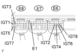
| E11-3 (IGT1) - E8-17 (IGT1) | Below 1 Ω |
| E37-3 (IGT2) - E6-13 (IGT2) | Below 1 Ω |
| E14-3 (IGT3) - E8-16 (IGT3) | Below 1 Ω |
| E35-3 (IGT4) - E6-12 (IGT4) | Below 1 Ω |
| E17-3 (IGT5) - E8-27 (IGT5) | Below 1 Ω |
| E30-3 (IGT6) - E6-11 (IGT6) | Below 1 Ω |
| E20-3 (IGT7) - E8-26 (IGT7) | Below 1 Ω |
| E28-3 (IGT8) - E6-10 (IGT8) | Below 1 Ω |
| E11-3 (IGT1) or E8-17 (IGT1) - Body ground | 10 kΩ or higher |
| E37-3 (IGT2) or E6-13 (IGT2) - Body ground | 10 kΩ or higher |
| E14-3 (IGT3) or E8-16 (IGT3) - Body ground | 10 kΩ or higher |
| E35-3 (IGT4) or E6-12 (IGT4) - Body ground | 10 kΩ or higher |
| E17-3 (IGT5) or E8-27 (IGT5) - Body ground | 10 kΩ or higher |
| E30-3 (IGT6) or E6-11 (IGT6) - Body ground | 10 kΩ or higher |
| E20-3 (IGT7) or E8-26 (IGT7) - Body ground | 10 kΩ or higher |
| E28-3 (IGT8) or E6-10 (IGT8) - Body ground | 10 kΩ or higher |
|
| ||||
| OK | |
| 6.CHECK ECM (IGT1, IGT2, IGT3, IGT4, IGT5, IGT6, IGT7, IGT8 VOLTAGE) |
 |
Measure the voltage of the ECM connectors when the engine is cranked.
| Tester Connection | Specified Condition |
| E8-17 (IGT1) - E6-7 (E1) | 0.1 to 4.5 V |
| E6-13 (IGT2) - E6-7 (E1) | 0.1 to 4.5 V |
| E8-16 (IGT3) - E6-7 (E1) | 0.1 to 4.5 V |
| E6-12 (IGT4) - E6-7 (E1) | 0.1 to 4.5 V |
| E8-27 (IGT5) - E6-7 (E1) | 0.1 to 4.5 V |
| E6-11 (IGT6) - E6-7 (E1) | 0.1 to 4.5 V |
| E8-26 (IGT7) - E6-7 (E1) | 0.1 to 4.5 V |
| E6-10 (IGT8) - E6-7 (E1) | 0.1 to 4.5 V |
|
| ||||
| OK | |
| 7.CHECK IGNITION COIL (POWER SOURCE) |
 |
Disconnect the E11, E14, E17, E20, E28, E30, E35 and E37 ignition coil connectors.
Turn the engine switch from on (IG) to start.
Measure the voltage of the wire harness side connector.
| Tester Connection | Specified Condition |
| E11-1 (+B) - Body ground | 9 to 14 V |
| E37-1 (+B) - Body ground | 9 to 14 V |
| E14-1 (+B) - Body ground | 9 to 14 V |
| E35-1 (+B) - Body ground | 9 to 14 V |
| E17-1 (+B) - Body ground | 9 to 14 V |
| E30-1 (+B) - Body ground | 9 to 14 V |
| E20-1 (+B) - Body ground | 9 to 14 V |
| E28-1 (+B) - Body ground | 9 to 14 V |
|
| ||||
| NG | |
| 8.CHECK WIRE HARNESS (IGNITION COIL - IG2 RELAY) |
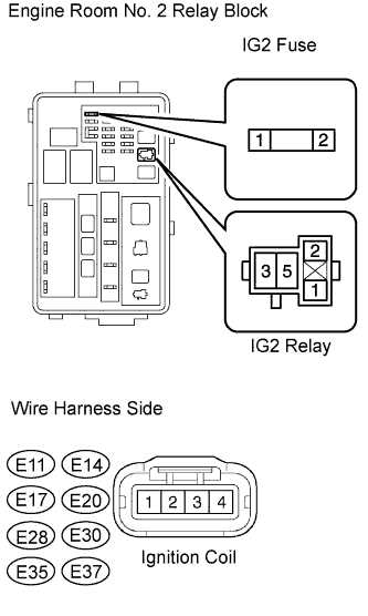 |
Inspect the IG2 fuse.
Remove the IG2 fuse from the engine room No. 2 relay block.
Measure the resistance of the IG2 fuse.
Disconnect the E11, E14, E17, E20, E28, E30, E35 and E37 ignition coil connectors.
Remove the IG2 relay from the engine room No. 2 relay block.
Measure the resistance of the wire harness side connectors.
| Tester Connection | Specified Condition |
| E11-1 (+B) - Relay block IG2 relay terminal 3 | Below 1 Ω |
| E37-1 (+B) - Relay block IG2 relay terminal 3 | Below 1 Ω |
| E14-1 (+B) - Relay block IG2 relay terminal 3 | Below 1 Ω |
| E35-1 (+B) - Relay block IG2 relay terminal 3 | Below 1 Ω |
| E17-1 (+B) - Relay block IG2 relay terminal 3 | Below 1 Ω |
| E30-1 (+B) - Relay block IG2 relay terminal 3 | Below 1 Ω |
| E20-1 (+B) - Relay block IG2 relay terminal 3 | Below 1 Ω |
| E28-1 (+B) - Relay block IG2 relay terminal 3 | Below 1 Ω |
| E11-1 (+B) or Relay block IG2 relay terminal 3 - Body ground | 10 kΩ or higher |
| E37-1 (+B) or Relay block IG2 relay terminal 3 - Body ground | 10 kΩ or higher |
| E14-1 (+B) or Relay block IG2 relay terminal 3 - Body ground | 10 kΩ or higher |
| E35-1 (+B) or Relay block IG2 relay terminal 3 - Body ground | 10 kΩ or higher |
| E17-1 (+B) or Relay block IG2 relay terminal 3 - Body ground | 10 kΩ or higher |
| E30-1 (+B) or Relay block IG2 relay terminal 3 - Body ground | 10 kΩ or higher |
| E20-1 (+B) or Relay block IG2 relay terminal 3 - Body ground | 10 kΩ or higher |
| E28-1 (+B) or Relay block IG2 relay terminal 3 - Body ground | 10 kΩ or higher |
|
| ||||
| OK | ||
| ||
