DTC P0300 Random / Multiple Cylinder Misfire Detected |
DTC P0301 Cylinder 1 Misfire Detected |
DTC P0302 Cylinder 2 Misfire Detected |
DTC P0303 Cylinder 3 Misfire Detected |
DTC P0304 Cylinder 4 Misfire Detected |
DTC P0305 Cylinder 5 Misfire Detected |
DTC P0306 Cylinder 6 Misfire Detected |
DTC P0307 Cylinder 7 Misfire Detected |
DTC P0308 Cylinder 8 Misfire Detected |
| DTC No. | DTC Detection Condition | Trouble Area |
| P0300 | Misfiring of random cylinder is detected |
|
| P0301 P0302 P0303 P0304 P0305 P0306 P0307 P0308 | Misfiring of each cylinder is detected | Same as DTC No. P0300 |
| Engine RPM | Time |
| Idling | 3.5 minutes or more |
| 1,000 rpm | 3 minutes or more |
| 2,000 rpm | 1.5 minutes or more |
| 3,000 rpm | 1 minute or more |
| 1.CHECK OTHER DTC OUTPUT |
Connect the intelligent tester to the DLC3.
Enter the following menus: Powertrain / Engine / DTC.
Read the DTCs.
| Display (DTC output) | Proceed to |
| P0300, P0301, P0302, P0303, P0304, P0305, P0306, P0307 or P0308 | A |
| P0300, P0301, P0302, P0303, P0304, P0305, P0306, P0307 or P0308 and other DTCs | B |
|
| ||||
| A | |
| 2.CHECK MISFIRE RPM AND MISFIRE LOAD |
Read and note the Misfire RPM and the Misfire Load (engine load) with the Data List.
| NEXT | |
| 3.CHECK CONNECTION OF PCV HOSE |
|
| ||||
| OK | |
| 4.CHECK MISFIRE COUNT (CYL #1, #2, #3, #4, #5, #6, #7, #8) |
Clear the DTCs.
Enter the following menus: Powertrain / Engine / Data List / Primary / Cylinder #1 (to #8) Misfire Rate.
Allow the engine to idle.
Read the misfire count of the cylinders #1 to #8.
If no misfire is counted for all of the cylinders, move the shift lever into the D position and repeat the 2 previous steps.
If misfires are still not counted, perform the next 2 steps.
Drive the vehicle with Misfire RPM and Misfire Load selected in the Data List.
Read the misfire count of cylinders #1 to #8, or check for any output DTCs.
| Misfire count in each cylinder | Proceed to |
| 1 or 2 cylinders have some misfire counts | A |
| 3 cylinders or more have some misfire counts | B |
|
| ||||
| A | |
| 5.PERFORM ACTIVE TEST (FUEL CUT #1 TO #8) |
Allow the engine to idle.
Enter the following menus: Powertrain / Engine / Active Test / Control the Cylinder #1 (to #8) Fuel Cut.
If a cylinder has a high misfire count, cut fuel to the cylinder. Compare the misfire count of the cylinder before fuel cut and after fuel cut.
| Misfire count in each cylinder | Proceed to |
| Misfire count of the cylinder before fuel cut and after fuel cut are roughly the same | A |
| Misfire count of the cylinder before fuel cut is lower than after fuel cut | B |
|
| ||||
| A | |
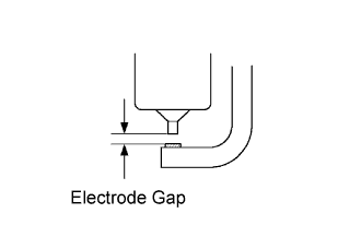
| 6.INSPECT SPARK PLUG |
 |
Remove the engine cover.
Remove the ignition coil and the spark plug of the misfire cylinder.
Measure the spark plug electrode gap.
Check the electrode for carbon deposits.
| Manufacturer | Spark Plug Type |
| DENSO | SK20R11 |
| NGK | IFR6A11 |
|
| ||||
| OK | |
| 7.CHECK SPARK AND IGNITION |
 |
Disconnect the injector connectors to prevent the engine from starting.
Install the spark plug to the ignition coil.
Attach the spark plug to the cylinder head cover.
Crank the engine for 2 seconds or less and check if a spark occurs.
|
| ||||
| OK | |
| 8.CHECK CYLINDER COMPRESSION PRESSURE ON MISFIRING CYLINDER |
Measure the cylinder compression pressure of the misfiring cylinder.
|
| ||||
| NG | ||
| ||
| 9.CHANGE NORMAL SPARK PLUG AND CHECK SPARK OF MISFIRING CYLINDER |
For inspection purposes, remove the current spark plug and install a normally functioning spark plug.
Perform a spark test.
Install the spark plug to the ignition coil and connect the ignition coil connector.
Disconnect the injector connector.
Ground the spark plug.
Check if a spark occurs while the engine is being cranked.
|
| ||||
| NG | ||
| ||
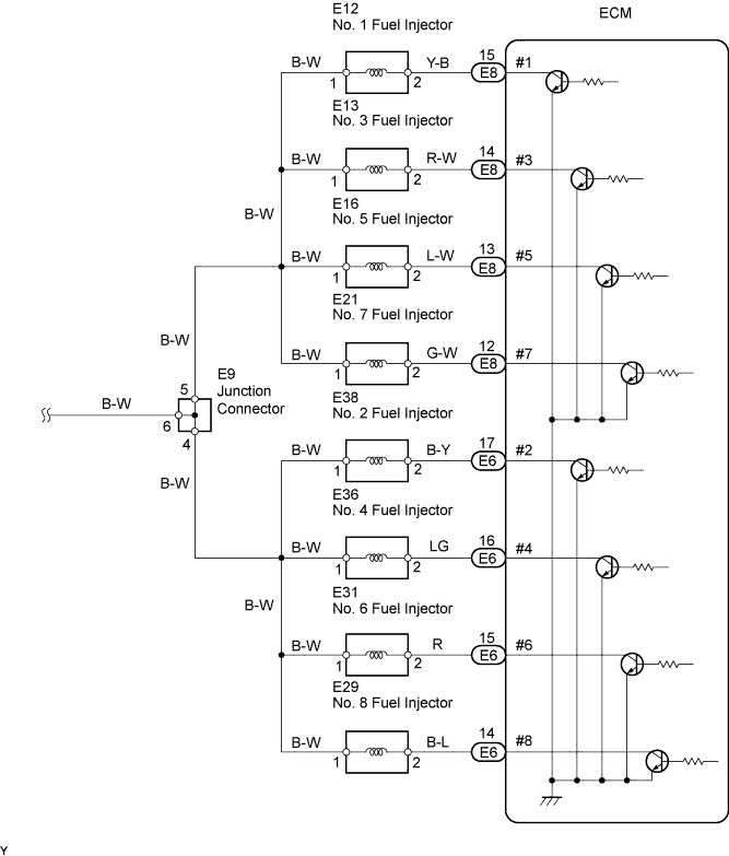
| 10.CHECK ECM (#1, #2, #3, #4, #5, #6, #7, #8 VOLTAGE) |
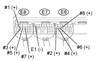 |
Turn the engine switch on (IG).
Measure the voltage of the ECM connectors.
| Tester Connection | Specified Condition |
| E8-15 (#1) - E6-7 (E1) | 9 to 14 V |
| E6-17 (#2) - E6-7 (E1) | 9 to 14 V |
| E8-14 (#3) - E6-7 (E1) | 9 to 14 V |
| E6-16 (#4) - E6-7 (E1) | 9 to 14 V |
| E8-13 (#5) - E6-7 (E1) | 9 to 14 V |
| E6-15 (#6) - E6-7 (E1) | 9 to 14 V |
| E8-12 (#7) - E6-7 (E1) | 9 to 14 V |
| E6-14 (#8) - E6-7 (E1) | 9 to 14 V |
|
| ||||
| NG | |
| 11.CHECK WIRE HARNESS (INJECTOR - ECM) |
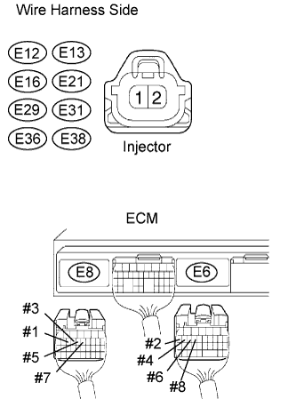 |
Disconnect the connector of the misfire cylinder and the E6 and E8 ECM connectors.
Turn the engine switch on (IG).
Measure the resistance and voltage of the wire harness side connectors.
| Cylinder | Tester Connection | Specified Condition |
| No. 1 | E12-1 - Ground | 11 to 14 V |
| No. 2 | E38-1 - Ground | 11 to 14 V |
| No. 3 | E13-1 - Ground | 11 to 14 V |
| No. 4 | E36-1 - Ground | 11 to 14 V |
| No. 5 | E16-1 - Ground | 11 to 14 V |
| No. 6 | E31-1 - Ground | 11 to 14 V |
| No. 7 | E21-1 - Ground | 11 to 14 V |
| No. 8 | E29-1 - Ground | 11 to 14 V |
| Cylinder | Tester Connection | Specified Condition |
| No. 1 | E12-2 - Ground | 10 kΩ or higher |
| No. 1 | E12-2 - E8-15 (#1) | Below 1 Ω |
| No. 2 | E38-2 - Ground | 10 kΩ or higher |
| No. 2 | E38-2 - E6-17 (#2) | Below 1 Ω |
| No. 3 | E13-2 - Ground | 10 kΩ or higher |
| No. 3 | E13-2 - E8-14 (#3) | Below 1 Ω |
| No. 4 | E36-2 - Ground | 10 kΩ or higher |
| No. 4 | E36-2 - E6-16 (#4) | Below 1 Ω |
| No. 5 | E16-2 - Ground | 10 kΩ or higher |
| No. 5 | E16-2 - E8-13 (#5) | Below 1 Ω |
| No. 6 | E31-2 - Ground | 10 kΩ or higher |
| No. 6 | E31-2 - E6-15 (#6) | Below 1 Ω |
| No. 7 | E21-2 - Ground | 10 kΩ or higher |
| No. 7 | E21-2 - E8-12 (#7) | Below 1 Ω |
| No. 8 | E29-2 - Ground | 10 kΩ or higher |
| No. 8 | E29-2 - E6-14 (#8) | Below 1 Ω |
|
| ||||
| OK | |
| 12.CHECK FUEL INJECTOR OF MISFIRING CYLINDER |
|
| ||||
| OK | |
| 13.CHECK VALVE CLEARANCE OF MISFIRING CYLINDER |
|
| ||||
| OK | |
| 14.CHECK AIR INDUCTION SYSTEM |
|
| ||||
| OK | |
| 15.CHECK VALVE TIMING |
 |
Remove the engine cover.
Remove the drive belt.
Remove the timing belt cover LH and RH.
Turn the crankshaft to align the matchmarks of the crankshaft.
Align the notch of the crankshaft pulley with the "0" position.
Confirm whether the matchmarks of the camshaft pulley and cylinder head cover are facing each other.
If the matchmarks are not facing each other, turn the crankshaft clockwise by 360°. Confirm again if the matchmarks are facing each other.
|
| ||||
| OK | |
| 16.CHECK FUEL PRESSURE |
|
| ||||
| OK | |
| 17.READ DATA LIST (COOLANT TEMP) |
Connect the intelligent tester to the DLC3.
Enter the following menus: Powertrain / Engine / Data List / Primary / Coolant Temp.
Read the Coolant Temp value when the engine is cold and warmed up.
|
| ||||
| OK | |
| 18.READ DATA LIST (MAF) |
Enter the following menus: Powertrain / Engine / Data List / Primary / Coolant Temp and MAF.
Allow the engine to idle until the ECT reaches 75°C (167°F).
Read the MAF value at idle rpm and 3,000 rpm.
|
| ||||
| OK | ||
| ||
