DTC    P0420    Catalyst System Efficiency Below Threshold (Bank 1)

DTC    P0430    Catalyst System Efficiency Below Threshold (Bank 2)

for Preparation Click here


MONITOR DESCRIPTION

The ECM uses heated oxygen sensors mounted before and after the Three-Way Catalyst (TWC) to monitor its efficiency. The front sensor sends pre-catalyst air-fuel information to the ECM. The rear sensor sends post-catalyst information to the ECM. The ECM compares these 2 signals to judge the efficiency of the catalyst and the catalyst's ability to store oxygen. During normal operation, the TWC stores and releases oxygen as needed. The capacity to store oxygen results in a low variation in the post-TWC exhaust stream as shown below.
If the catalyst is functioning normally, the waveform of the heated oxygen sensor (sensor 2) slowly switches between RICH and LEAN. If the catalyst is deteriorated, the waveform will alternate frequently between RICH and LEAN.
As the catalyst efficiency degrades, its ability to store oxygen is reduced and the catalyst output becomes more variable.
When running the catalyst monitor, the ECM begins to measure the signal length of the heated oxygen sensor (sensor 1) and heated oxygen sensor (sensor 2). The ECM calculates the rate of the signal length of the heated oxygen sensor (sensor 1) and heated oxygen sensor (sensor 2) (catalyst deterioration level). If the catalyst deterioration level exceeds the threshold, the ECM interprets this as a catalyst malfunction. The ECM illuminates the MIL (2 trip detection logic) and sets a DTC.
The monitor runs after:
  1. The engine is warmed up (Engine Coolant Temperature (ECT) is 75°C (167°F) or more).
  2. The vehicle is driven at approximately 60 to 100 km/h (37 to 63 mph) for 15 minutes.

A083860E06


A082718E04


DTC No.
DTC Detection Condition
Trouble Area
P0420
P0430
  1. After engine and TWC warmed up, and while vehicle is driven within set value and engine RPM ranges
  2. Waveforms of heated oxygen sensor (sensor 2) alternates frequency between RICH and LEAN (2 trip detection logic)
  1. Heated oxygen sensor (sensor 1)
  2. Heated oxygen sensor (sensor 2)
  3. Gas leakage in exhaust system
  4. TWC

CONFIRMATION DRIVING PATTERN


A054279E03

  1. Connect the intelligent tester to the DLC3.
  2. Start the engine and warm it up with all the accessories switched OFF until the ECT becomes stable.
  3. Run the engine at 2,500 to 3,000 rpm for about 3 minutes.

    HINT:
    Control the engine RPM so that the calculated catalyst temperature can be between 550 and 800°C (1,022 and 1,472°F). The calculated catalyst temperatures of bank 1 and bank 2 can be read by viewing CAT TEMP B1 S1 and CAT TEMP B2 S1 of the Data List.


  4. A093282E13
    Confirm that heated oxygen sensor (bank 1 sensor 1 (OX1A) and bank 2 sensor 1 (OX2A)) have waveforms that are around 0.5 V during feedback to the ECM. Then check the waveform of the heated oxygen sensor (bank 1 sensor 2 (OX1B) and bank 2 sensor 2 (OX2B)) for the same waveforms (0.5 V during feedback).

    HINT:
    If there is a malfunction in the catalyst, the waveform of the heated oxygen sensor (sensor 2) (OX1B, OX2B) is almost the same as that of the heated oxygen sensor (sensor 1) (OX1A, OX2A), which is shown.


WIRING DIAGRAM


A105223E02


A105224E04


INSPECTION PROCEDURE

HINT:
  1. Read freeze frame data using the intelligent tester. Freeze frame data records the engine conditions when a malfunction is detected. When troubleshooting, freeze frame data can help determine if the vehicle was running or stopped, if the engine was warmed up or not, if the air-fuel ratio was LEAN or RICH, and other data from the time the malfunction occurred.
  2. If DTC P0420 is displayed, check the bank 1 catalyst.
  3. If DTC P0430 is displayed, check the bank 2 catalyst.
  4. Bank 1 includes cylinder No. 1, but bank 2 does not. Cylinder No. 1 is located in the front part of the engine, opposite the transmission.

1.CHECK OTHER DTC OUTPUT (IN ADDITION TO DTC P0420, P0430)
  1. Connect the intelligent tester to the DLC3.

  1. Turn the engine switch on (IG) and turn the tester ON.

  1. Enter the following menus: Powertrain / Engine / DTC.

  1. Read the DTCs.

    Result:

    Display (DTC output)
    Proceed to
    P0420 or P0430
    A
    P0420 or P0430 and other DTCs
    B


B
GO TO RELEVANT DTC CHART
A


2.CHECK FOR EXHAUST GAS LEAKAGE


NG
REPAIR OR REPLACE EXHAUST GAS LEAKAGE POINT
OK


3.INSPECT HEATED OXYGEN SENSOR (RESISTANCE)
A113353E01
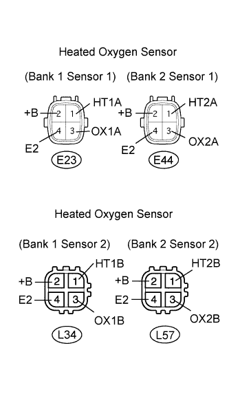
  1. Disconnect the E23, E44, L34 and L57 sensor connectors.

  1. Measure the resistance of the sensor.

    Standard resistance: Sensor 1:
    Tester Connection
    Specified Condition
    1 (HT1A) - 2 (+B)
    11 to 16 Ω
    1 (HT2A) - 2 (+B)
    11 to 16 Ω
    1 (HT1A) - 4 (E2)
    10 kΩ or higher
    1 (HT2A) - 4 (E2)
    10 kΩ or higher

    Standard resistance: Sensor 2:
    Tester Connection
    Specified Condition
    1 (HT1B) - 2 (+B)
    11 to 16 Ω
    1 (HT2B) - 2 (+B)
    11 to 16 Ω
    1 (HT1B) - 4 (E2)
    10 kΩ or higher
    1 (HT2B) - 4 (E2)
    10 kΩ or higher


NG
REPLACE HEATED OXYGEN SENSOR
OK


4.PERFORM ACTIVE TEST

HINT:
It is possible that the malfunctioning area can be found using the Active Test Control operation. The Active Test can determine if the heated oxygen sensor or other potential trouble areas are malfunctioning or not.
The injection volume can be switched to -12.5% (decrease) or +25% (increase) by the Active Test.
The Active Test procedure enables a technician to check and graph the voltage outputs of the heated oxygen sensors.

  1. Procedure:
    1. Connect the intelligent tester to the DLC3.
    2. Turn the engine switch on (IG).
    3. Warm up the engine by running the engine at 2,500 rpm for approximately 90 seconds.
    4. Enter the following menus: Powertrain / Engine / Active Test / Control the Injection Volume.
    5. Perform the Active Test while the engine is idling.

Standard:
Heated oxygen sensor reacts in accordance with the increase and decrease of injection volume:
+25% → output: More than 0.55 V
-12.5% → output: Less than 0.4 V

NOTICE:
The heated oxygen sensor (sensor 1) output has a few seconds of delay and the heated oxygen sensor (sensor 2) output has a maximum of 20 seconds of delay.
If the vehicle is short on fuel, the air-fuel ratio becomes LEAN and the DTCs will be recorded.


Case
Heated Oxygen Sensor (sensor 1) Voltage
Heated Oxygen Sensor (sensor 2) Voltage
Main Suspected Trouble Area
1
Injection Volume
+25%
-12.5%
A103184
Injection Volume
+25%
-12.5%
A103184
-
Heated Oxygen Sensor Voltage
0.55 V or more
Below 0.4 V
A103187
Heated Oxygen Sensor Voltage
0.5 V or more
Below 0.4 V
A103186
2
Injection Volume
+25%
-12.5%
A103184
Injection Volume
+25%
-12.5%
A103184
Heated oxygen sensor (sensor 1)
Heated oxygen sensor heater (sensor 1)
Heated Oxygen Sensor Voltage
Almost
no reaction
A103185
Heated Oxygen Sensor Voltage
0.5 V or more
Below 0.4 V
A103186
3
Injection Volume
+25%
-12.5%
A103184
Injection Volume
+25%
-12.5%
A103184
Heated oxygen sensor (sensor 2)
Heated oxygen sensor heater (sensor 2)
Heated Oxygen Sensor Voltage
0.55 V or more
Below 0.4 V
A103187
Heated Oxygen Sensor Voltage
Almost
no reaction
A103185
4
Injection volume
+25%
-12.5%
A103184
Injection Volume
+25%
-12.5%
A103184
Injector fuel pressure, Exhaust gas leak, etc.
(air-fuel ratio is extremely LEAN or RICH)
Heated Oxygen Sensor Voltage
Almost
no reaction
A103185
Heated Oxygen Sensor Voltage
Almost
no reaction
A103185


NG
REPLACE HEATED OXYGEN SENSOR
OK


5.REPLACE CATALYST CONVERTER (BANK 1 OR BANK 2) AND FRONT EXHAUST PIPE

NOTICE:
Replace both the front catalyst and rear catalyst (front exhaust pipe) of the damaged bank.


NEXT

END