SFI SYSTEM > ECM Power Source Circuit |


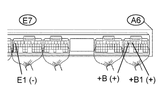
| 1.CHECK ECM (+B, +B1 VOLTAGE) |
 |
Turn the engine switch on (IG).
Measure the voltage of the ECM connectors.
| Tester Connection | Specified Condition |
| A6-6 (+B) - E7-7 (E1) | 9 to 14 V |
| A6-5 (+B1) - E7-7 (E1) | 9 to 14 V |
|
| ||||
| NG | |
| 2.CHECK WIRE HARNESS (ECM - BODY GROUND) |
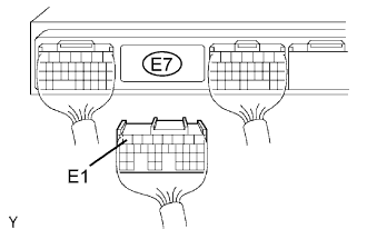 |
Disconnect the E7 ECM connector.
Measure the resistance of the wire harness side connector.
| Tester Connection | Specified Condition |
| E7-7 (E1) - Body ground | Below 1 Ω |
|
| ||||
| OK | |
| 3.CHECK ECM (IGSW VOLTAGE) |
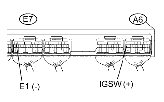 |
Turn the engine switch on (IG).
Measure the voltage of the ECM connectors.
| Tester Connection | Specified Condition |
| A6-17 (IGSW) - E7-7 (E1) | 9 to 14 V |
|
| ||||
| NG | |
| 4.INSPECT FUSE (IGN) |
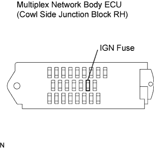 |
Remove the IGN fuse from the body ECU.
Measure the resistance of the IGN fuse.
|
| ||||
| OK | |
| 5.INSPECT RELAY (Marking: IG2) |
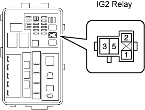 |
Remove the IG2 relay from engine room No. 2 relay block.
Measure the resistance of the IG2 relay.
| Tester Connection | Specified Condition |
| 3 - 5 | 10 kΩ or higher |
| 3 - 5 | Below 1 Ω (when battery voltage is applied to terminals 1 and 2) |
|
| ||||
| OK | ||
| ||
| 6.CHECK ECM (MREL VOLTAGE) |
 |
Turn the engine switch on (IG).
Measure the voltage of the ECM connectors.
| Tester Connection | Specified Condition |
| A6-13 (MREL) - E7-7 (E1) | 9 to 14 V |
|
| ||||
| OK | |
| 7.INSPECT FUSE (EFI) |
 |
Remove the EFI fuse from the engine room No. 2 relay block.
Measure the resistance of the EFI fuse.
|
| ||||
| OK | |
| 8.INSPECT INTEGRATION RELAY (Marking: EFI MAIN) |
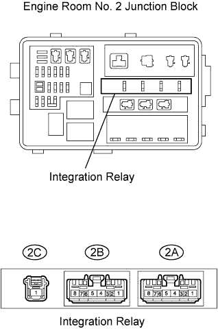 |
Remove the integration relay from the engine room No. 2 junction block.
Measure the resistance of the EFI MAIN relay.
| Terminal Connections | Specified Condition |
| 2A-8 - 2C-1 | 10 kΩ or higher |
| 2A-8 - 2C-1 | Below 1 Ω (when battery voltage is applied to terminals 2A-6 and 2A-7) |
|
| ||||
| OK | |
| 9.CHECK WIRE HARNESS (INTEGRATION RELAY - ECM, INTEGRATION RELAY - BODY GROUND) |
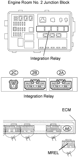 |
Check the wire harness between the integration relay and the ECM.
Remove the integration relay from the engine room No. 2 junction block
Disconnect the A6 ECM connector.
Measure the resistance of the wire harness side connectors.
| Tester Connection | Specified Condition |
| 2A-6 - A6-13 (MREL) | Below 1 Ω |
| 2A-6 or A6-13 (MREL) - Body ground | 10 kΩ or higher |
Check the wire harness between the integration relay and body ground.
Remove the integration relay from the engine room No. 2 junction block.
Measure the resistance of the wire harness side connectors.
| Tester Connection | Specified Condition |
| 2A-7 - Body ground | Below 1 Ω |
|
| ||||
| OK | ||
| ||
