POWER DOOR LOCK CONTROL SYSTEM > All Doors LOCK / UNLOCK Functions do not Operate Via Master Switch, Driver Side Door Key Cylinder |


| 1.INSPECT FUSE (FR DOOR LH*1, FR DOOR RH*2, MPX-B, D/C CUT) |
Remove the FR DOOR LH*1 fuse from the cowl side junction block LH.
Remove the FR DOOR EGH*2 fuse from the cowl side junction block RH.
Remove the MPX-B and D/C CUT fuses from the engine room No. 1 junction block.
Measure the resistance of the fuses.
|
| ||||
| OK | |
| 2.CHECK WIRE HARNESS (DRIVER DOOR ECU - BATTERY AND BODY GROUND) |
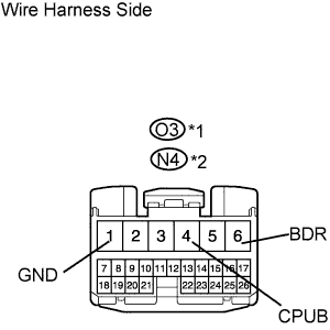 |
Disconnect the O3*1 or N4*2 ECU connector.
Measure the voltage of the wire harness side connector.
| Tester Connection | Specified Condition |
| O3-4 (CPUB) - Body ground | 10 to 14 V |
| O3-6 (BDR) - Body ground | 10 to 14 V |
| Tester Connection | Specified Condition |
| N4-4 (CPUB) - Body ground | 10 to 14 V |
| N4-6 (BDR) - Body ground | 10 to 14 V |
Measure the resistance of the wire harness side connector.
| Tester Connection | Specified Condition |
| O3-1 (GND) - Body ground | Below 1 Ω |
| Tester Connection | Specified Condition |
| N4-1 (GND) - Body ground | Below 1 Ω |
|
| ||||
| OK | |
| 3.CHECK DOOR LOCK OPERATION |
| Result | Proceed to |
| Doors cannot be locked through master switch | A |
| Doors cannot be locked through driver side door key cylinder | B |
|
| ||||
| A | |
| 4.REPLACE MULTIPLEX NETWORK MASTER SWITCH ASSEMBLY (POWER WINDOW REGULATOR MASTER SWITCH ASSEMBLY) |
After replacing the multiplex network master switch assembly with a normal one, check that all doors can be locked and unlocked by using the master switch.
|
| ||||
| OK | ||
| ||
| 5.READ VALUE OF INTELLIGENT TESTER (DOOR LOCK AND UNLOCK SWITCH) |
Check the Data List for proper functioning of the door lock and unlock switch.
| Item | Measurement Item/Display (Range) | Normal Condition | Diagnostic Note |
| Door Key Lock | Door key-linked lock switch signal/ ON or OFF | ON: Driver side door key cylinder is turned to lock position OFF: Driver side door key cylinder is turned to unlock position | - |
| Door Key Unlock | Door key-linked unlock switch signal/ ON or OFF | ON: Driver side door key cylinder is turned to unlock position OFF: Driver side door key cylinder is turned to lock position | - |
|
| ||||
| OK | ||
| ||
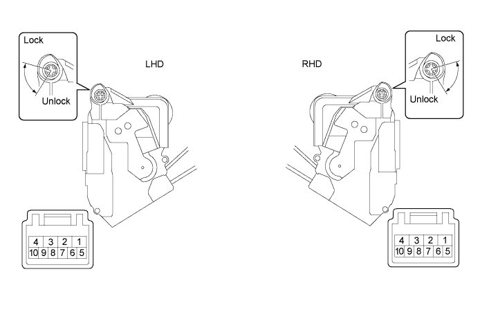
| 6.INSPECT FRONT DOOR LOCK ASSEMBLY (DRIVER SIDE) (DOOR LOCK AND UNLOCK SWITCH) |
Disconnect the O6*1 or N6*2 door lock connector.
Measure the resistance of the switch.
| Tester Connection | Condition | Specified Condition |
| 9 - 7 | Lock | Below 1 Ω |
| 10 - 7 | Unlock | Below 1 Ω |
| 9 - 7 | OFF | 10 kΩ or higher |
| 10 - 7 | OFF | 10 kΩ or higher |
| Tester Connection | Condition | Specified Condition |
| 6 - 8 | Lock | Below 1 Ω |
| 5 - 8 | Unlock | Below 1 Ω |
| 6 - 8 | OFF | 10 kΩ or higher |
| 5 - 8 | OFF | 10 kΩ or higher |
|
| ||||
| OK | |
| 7.CHECK WIRE HARNESS (FRONT DOOR LOCK ASSEMBLY - MULTIPLEX NETWORK MASTER SWITCH) |
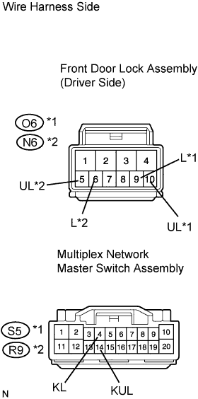 |
Disconnect the O6*1 or N6*2 door lock connector.
Disconnect the S5*1 or R9*2 switch connector.
Measure the resistance of the wire harness side connectors.
| Tester Connection | Specified Condition |
| O6-9 (L) - S5-4 (KL) | Below 1 Ω |
| O6-10 (UL) - S5-14 (KUL) | Below 1 Ω |
| Tester Connection | Specified Condition |
| N6-6 (L) - R9-4 (KL) | Below 1 Ω |
| N6-5 (UL) - R9-14 (KUL) | Below 1 Ω |
|
| ||||
| OK | |
| 8.CHECK WIRE HARNESS (DRIVER DOOR ECU - FRONT DOOR LOCK ASSEMBLY (DRIVER SIDE)) |
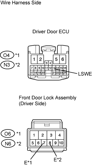 |
Disconnect the O3*1 or N4*2 ECU connector.
Disconnect the O6*1 or N6*2 door lock connector.
Measure the resistance of the wire harness side connectors.
| Tester Connection | Specified Condition |
| O4-13 (LSWE) - O6-7 (E) | Below 1 Ω |
| Tester Connection | Specified Condition |
| N3-13 (LSWE) - N6-8 (E) | Below 1 Ω |
|
| ||||
| OK | |
| 9.REPLACE DRIVER DOOR ECU |
After replacing the driver door ECU with a normal one, check that all doors can be locked and unlocked by using the driver side door key cylinder.
|
| ||||
| OK | ||
| ||
