AIR CONDITIONING SYSTEM > IG Power Source Circuit |

| 1.INSPECT FUSE (ECU-IG RH) |
Remove the ECU-IG RH fuse from the cowl side junction block RH.
Measure the resistance of the fuse.
| Tester Item | Condition | Specified Condition |
| ECU-IG RH fuse | Always | Below 1 Ω |
|
| ||||
| OK | |
| 2.INSPECT AIR CONDITIONING AMPLIFIER (IG+ - GND) |
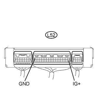 |
Remove the A/C amplifier with its connectors still connected.
Turn the engine switch on (IG).
Measure the voltage of the connector.
| Tester Connection | Condition | Specified Condition |
| L52-21 (IG+) - L52-20 (GND) | Engine switch on (IG) | 10 to 14 V |
|
| ||||
| OK | ||
| ||
| 3.CHECK WIRE HARNESS (AIR CONDITIONING AMPLIFIER - BATTERY) |
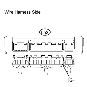 |
Disconnect the L52 A/C amplifier connector.
Measure the voltage of the wire harness side connector.
| Tester Connection | Condition | Specified Condition |
| L52-21 (IG+) - Body ground | Engine switch off | Below 1.0 V |
| Engine switch on (IG) | 10 to 14 V |
|
| ||||
| OK | |
| 4.CHECK WIRE HARNESS (AIR CONDITIONING AMPLIFIER - BODY GROUND) |
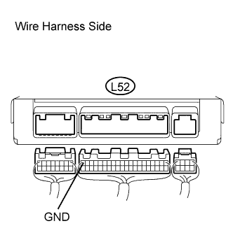 |
Disconnect the L52 A/C amplifier connector.
Measure the resistance of the wire harness side connector.
| Tester Connection | Condition | Specified Condition |
| L52-20 (GND) - Body ground | Always | Below 1 Ω |
|
| ||||
| OK | ||
| ||
