AIR CONDITIONING SYSTEM > Blower Motor Circuit |

| 1.PERFORM ACTIVE TEST BY INTELLIGENT TESTER |
Connect the intelligent tester to the DLC3.
Turn the engine switch on (IG) and push the intelligent tester main switch on.
Select the item below in the Active Test and then check that the relay operates.
| Item | Test Details / Display (Range) | Diagnostic Note |
| Blower Motor (Blower Motor) | Blower motor / Min.: Level 0, Max.: Level 31 | - |
| OK | A |
| NG (blower motor does not operate) | B |
| NG (blower motor operates but does not change speed) | C |
|
| ||||
|
| ||||
| A | ||
| ||
| 2.INSPECT FUSE |
Remove the HEATER fuse and ALT fuse from the engine room No. 1 junction block.
Measure the resistance of the fuses.
| Tester Item | Condition | Specified Condition |
| HEATER fuse | Always | Below 1 Ω |
| ALT fuse | Always | Below 1 Ω |
|
| ||||
| OK | |
| 3.CHECK WIRE HARNESS (BLOWER MOTOR - BODY GROUND) |
 |
Disconnect the A50 or k1 blower motor connector.
Measure the resistance of the wire harness side connector.
| Tester Item | Condition | Specified Condition |
| A50-1 (GND) *1 - Body ground | Always | Below 1 Ω |
| k1-1 (GND) *2 - Body ground | Always | Below 1 Ω |
|
| ||||
| OK | |
| 4.CHECK WIRE HARNESS (BLOWER MOTOR - BATTERY) |
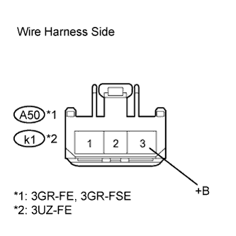 |
Disconnect the A50 or k1 blower motor connector.
Measure the voltage of the wire harness side connector.
| Tester Item | Condition | Specified Condition |
| A50-3 (+B) *1 - Body ground | Engine switch on (IG) | 10 to 14 V |
| k1-3 (+B) *2 - Body ground | Engine switch on (IG) | 10 to 14 V |
|
| ||||
| OK | |
| 5.CHECK BLOWER MOTOR |
 |
Disconnect the A/C amplifier connector.
Connect the blower motor connector.
Measure the voltage of the connector.
| Tester Item | Condition | Specified Condition |
| 2 (SI) - Body ground | Engine switch on (IG) | 4.5 to 5.5 V |
|
| ||||
| OK | |
| 6.CHECK WIRE HARNESS (A/C AMPLIFIER - BODY GROUND) |
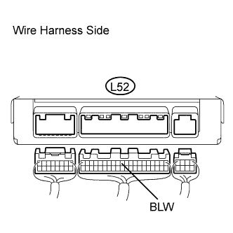 |
Disconnect the L52 A/C amplifier connector.
Measure the voltage of the wire harness side connector.
| Tester Item | Condition | Specified Condition |
| L52-11 (BLW) - Body ground | Engine switch on (IG) | 4.5 to 5.5 V |
|
| ||||
| OK | |
| 7.CHECK AIR CONDITIONING AMPLIFIER |
 |
Remove the A/C amplifier with its connectors still connected.
Turn the engine switch on (IG).
Turn the blower switch ON (Lo).
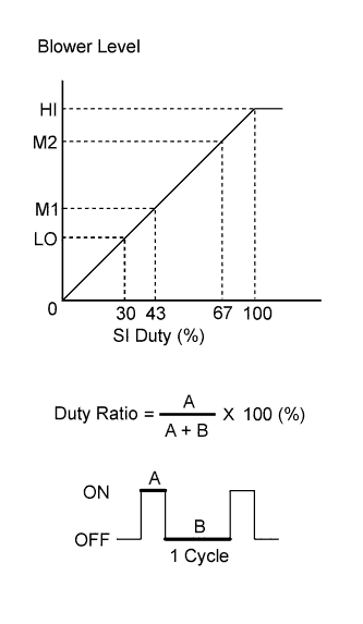
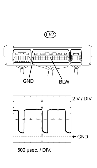
Measure the waveform between terminal L52-11 (BLW) of the A/C amplifier and body ground.
| Item | Contents |
| Tool setting | 2 V / DIV., 500 μs / DIV. |
| Vehicle condition | Engine switch on (IG) Blower switch ON (Lo) |
|
| ||||
| OK | ||
| ||
