DTC P0171 System Too Lean (Bank 1) |
DTC P0172 System Too Rich (Bank 1) |
DTC P0174 System Too Lean (Bank 2) |
DTC P0175 System Too Rich (Bank 2) |
| DTC No. | DTC Detection Condition | Trouble Area |
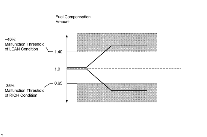
| P0171 P0174 | When air-fuel ratio feedback is stable after warming up engine, fuel trim is considerably in error on LEAN side (2 trip detection logic) |
|
| P0172 P0175 | When air-fuel ratio feedback is stable after warming up engine, fuel trim is considerably in error on RICH side (2 trip detection logic) |
|


| Case | Heated Oxygen Sensor (sensor 1) Voltage | Heated Oxygen Sensor (sensor 2) Voltage | Main Suspected Trouble Area | ||
| 1 | Injection Volume +25% -12.5% |  | Injection Volume +25% -12.5% | | - |
| Heated Oxygen Sensor Voltage 0.55 V or more Below 0.4 V |  | Heated Oxygen Sensor Voltage 0.5 V or more Below 0.4 V |  | ||
| 2 | Injection Volume +25% -12.5% | | Injection Volume +25% -12.5% | | Heated oxygen sensor (sensor 1) Heated oxygen sensor heater (sensor 1) |
| Heated Oxygen Sensor Voltage Almost no reaction |  | Heated Oxygen Sensor Voltage 0.5 V or more Below 0.4 V | | ||
| 3 | Injection Volume +25% -12.5% | | Injection Volume +25% -12.5% | | Heated oxygen sensor (sensor 2) Heated oxygen sensor heater (sensor 2) |
| Heated Oxygen Sensor Voltage 0.55 V or more Below 0.4 V | | Heated Oxygen Sensor Voltage Almost no reaction | | ||
| 4 | Injection volume +25% -12.5% | | Injection Volume +25% -12.5% | | Injector fuel pressure, Exhaust gas leak, etc. (air-fuel ratio is extremely LEAN or RICH) |
| Heated Oxygen Sensor Voltage Almost no reaction | | Heated Oxygen Sensor Voltage Almost no reaction | | ||
| 1.CHECK OTHER DTC OUTPUT (IN ADDITION TO DTC P0171, P0172, P0174, P0175) |
Connect the intelligent tester to the DLC3.
Turn the engine switch on (IG) and turn the tester ON.
Enter the following menus: Powertrain / Engine / DTC.
Read the DTCs.
| Display (DTC output) | Proceed to |
| P0171, P0172, P0174 or P0175 | A |
| P0171, P0172, P0174 or P0175 and other DTCs | B |
|
| ||||
| A | |
| 2.CHECK CONNECTION OF PCV HOSE |
|
| ||||
| OK | |
| 3.CHECK AIR INDUCTION SYSTEM |
Check the air induction system for vacuum leaks.
|
| ||||
| OK | |
| 4.PERFORM ACTIVE TEST (CONTROL) |
Perform the Active Test Control with the intelligent tester and check the heated oxygen sensor status.
| Related DTCs | Heated Oxygen Sensor Status | Condition and Heated Oxygen Sensor Condition | Misfire | Main Suspected Trouble Area | Go to Step | |||
| B1 S1 | B1 S2 | B2 S1 | B2 S2 | |||||
| N/A | L/R | L/R | L/R | L/R | Normal | None | None | N/A |
| P0171 P0174 | L | L | L | L | Actual is LEAN at all cylinders | May occur | PCV hose, air induction system, fuel pressure, MAF or ECT | A |
| P0172 P0175 | R | R | R | R | Actual is RICH at all cylinders | None | Fuel pressure, MAF or ECT | |
| P0171 | L | L | L/R | L/R | Actual is LEAN at bank 1 | May occur | Spark plug, ignition system, injector or exhaust gas leak | B |
| P0174 | L/R | L/R | L | L | Actual is LEAN at bank 2 | |||
| P0172 | R | R | L/R | L/R | Actual is RICH at bank 1 | None | Spark plug, ignition system or injector | C |
| P0175 | L/R | L/R | R | R | Actual is RICH at bank 2 | |||
| P0171 | L | R | L/R | L/R | Heated oxygen sensor (bank 1 sensor 1) malfunction | None | Heated oxygen sensor (bank 1 sensor 1) | D |
| P0174 | L/R | L/R | L | R | Heated oxygen sensor (bank 2 sensor 1) malfunction | None | Heated oxygen sensor (bank 2 sensor 1) | |
| P0172 | R | L | L/R | L/R | Heated oxygen sensor (bank 1 sensor 1) malfunction | None | Heated oxygen sensor (bank 1 sensor 1) | |
| P0175 | L/R | L/R | R | L | Heated oxygen sensor (bank 2 sensor 1) malfunction | None | Heated oxygen sensor (bank 2 sensor 1) | |
|
| ||||
|
| ||||
|
| ||||
|
| ||||
| 5.READ DATA LIST (COOLANT TEMP) |
Connect the intelligent tester to the DLC3.
Enter the following menus: Powertrain / Engine / Data List / Primary / Coolant Temp.
Read the Coolant Temp value when the engine is cold and warmed-up.
|
| ||||
| OK | |
| 6.READ DATA LIST (MAF) |
Enter the following menus: Powertrain / Engine / Data List / Primary / Coolant Temp and MAF.
Allow the engine to idle until the ECT reaches 75°C (167°F).
Read the MAF value at idle rpm and 3,000 rpm.
|
| ||||
| OK | |
| 7.CHECK FUEL PRESSURE |
Check the fuel pressure (Click here).
|
| ||||
| OK | |
| 8.CHECK FOR EXHAUST GAS LEAKAGE |
|
| ||||
| OK | |
| 9.CHECK FOR SPARK AND IGNITION |
|
| ||||
| OK | |
| 10.INSPECT FUEL INJECTOR |
|
| ||||
| OK | |
| 11.INSPECT HEATED OXYGEN SENSOR |
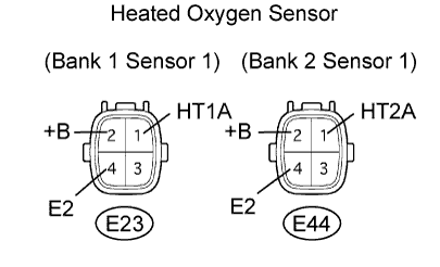 |
Disconnect the E23 and E44 sensor connectors.
Measure the resistance of the sensor.
| Tester Connection | Specified Condition |
| E23-1 (HT1A) - E23-2 (+B) | 11 to 16 Ω |
| E44-1 (HT2A) - E44-2 (+B) | 11 to 16 Ω |
| E23-1 (HT1A) - E23-4 (E2) | 10 kΩ or higher |
| E44-1 (HT2A) - E44-4 (E2) | 10 kΩ or higher |
|
| ||||
| OK | |
| 12.INSPECT INTEGRATION RELAY (EFI MAIN) |
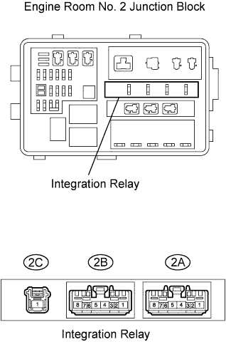 |
Remove the integration relay from the engine room No. 2 junction block.
Measure the resistance of the EFI MAIN relay.
| Terminal Connections | Specified Condition |
| 2A-8 - 2C-1 | 10 kΩ or higher |
| 2A-8 - 2C-1 | Below 1 Ω (when battery voltage is applied to terminals 2A-6 and 2A-7) |
|
| ||||
| OK | |
| 13.CHECK WIRE HARNESS (HEATED OXYGEN SENSOR (SENSOR 1) - ECM) |
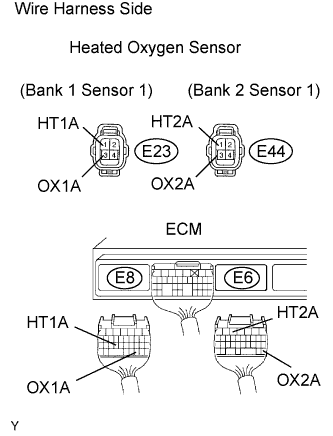 |
Disconnect the E23 and E44 sensor connectors.
Disconnect the E6 and E8 ECM connectors.
Measure the resistance of the wire harness side connectors.
| Tester Connection | Specified Condition |
| E23-1 (HT1A) - E8-24 (HT1A) | Below 1 Ω |
| E23-3 (OX1A) - E8-30 (OX1A) | Below 1 Ω |
| E44-1 (HT2A) - E6-5 (HT2A) | Below 1 Ω |
| E44-3 (OX2A) - E6-28 (OX2A) | Below 1 Ω |
| E23-1 (HT1A) or E8-24 (HT1A) - Body ground | 10 kΩ or higher |
| E23-3 (OX1A) or E8-30 (OX1A) - Body ground | 10 kΩ or higher |
| E44-1 (HT2A) or E6-5 (HT2A) - Body ground | 10 kΩ or higher |
| E44-3 (OX2A) or E6-28 (OX2A) - Body ground | 10 kΩ or higher |
|
| ||||
| OK | |
| 14.REPLACE HEATED OXYGEN SENSOR |
| NEXT | |
| 15.PERFORM CONFIRMATION DRIVING PATTERN |

| NEXT | ||
| ||
