LIGHTING SYSTEM > Door Courtesy Switch Circuit |

| 1.READ VALUE OF INTELLIGENT TESTER |
Check the Data List for proper functioning of the courtesy switch.
| Item | Measurement Item / Display (Range) | Normal Condition | Diagnostic Note |
| D Door Curtesy SW | Driver side courtesy switch / ON or OFF | ON: Driver side door is open OFF: Driver side door is closed | - |
| P Door Curtesy SW | Passenger side courtesy switch / ON or OFF | ON: Passenger side door is open OFF: Passenger side door is closed | - |
| Rr Door Curtesy SW | Rear (LH or RH) courtesy switch / ON or OFF | ON: Rear door (LH or RH) is open OFF: Rear door (LH or RH) is closed | - |
| Result | Proceed to |
| OK | A |
| Driver side door courtesy switch does not operate | B |
| Front passenger side door courtesy switch does not operate | C |
| Both rear door courtesy switches do not operate | D |
|
| ||||
|
| ||||
|
| ||||
| A | ||
| ||
| 2.INSPECT DOOR COURTESY SWITCH (DRIVER SIDE) |
|
| ||||
| OK | |
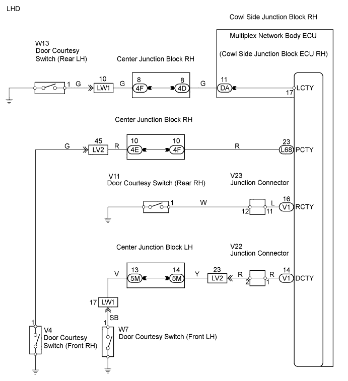
| 3.CHECK WIRE HARNESS (DOOR COURTESY SWITCH (DRIVER SIDE) - MULTIPLEX NETWORK BODY ECU) |
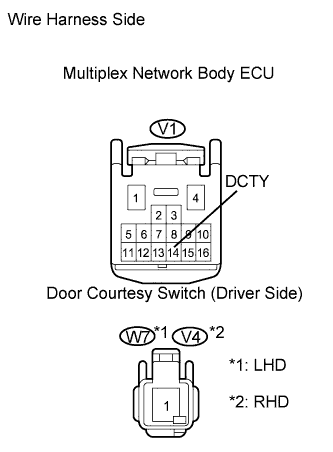 |
Disconnect the V1 ECU connector.
Disconnect the W7*1 or V4*2 switch connector.
Measure the resistance of the wire harness side connectors.
| Tester Connection | Specified Condition |
| V1-14 (DCTY) - W7-1 | Below 1 Ω |
| V1-14 (DCTY) or W7-1 - Body ground | 10 kΩ or higher |
| Tester Connection | Specified Condition |
| V1-14 (DCTY) - V4-1 | Below 1 Ω |
| V1-14 (DCTY) or V4-1 - Body ground | 10 kΩ or higher |
|
| ||||
| OK | ||
| ||
| 4.INSPECT DOOR COURTESY SWITCH (PASSENGER SIDE) |
|
| ||||
| OK | |
| 5.CHECK WIRE HARNESS (DOOR COURTESY SWITCH (PASSENGER SIDE) - MULTIPLEX NETWORK BODY ECU) |
 |
Disconnect the L68 ECU connector.
Disconnect the V4*1 or W7*2 switch connector.
Measure the resistance of the wire harness side connectors.
| Tester Connection | Specified Condition |
| L68-23 (PCTY) - V4-1 | Below 1 Ω |
| L68-23 (PCTY) or V4-1 - Body ground | 10 kΩ or higher |
| Tester Connection | Specified Condition |
| L68-23 (PCTY) - W7-1 | Below 1 Ω |
| L68-23 (PCTY) or W7-1 - Body ground | 10 kΩ or higher |
|
| ||||
| OK | ||
| ||
| 6.INSPECT DOOR COURTESY SWITCH (REAR LH OR REAR RH) |
|
| ||||
| OK | |
| 7.CHECK WIRE HARNESS (DOOR COURTESY SWITCH (REAR LH OR REAR RH) - COWL SIDE JUNCTION BLOCK RH OR MULTIPLEX NETWORK BODY ECU) |
 |
Check the wire harness between the cowl side junction block RH and door courtesy switch (rear LH).
Disconnect the DA junction block connector.
Disconnect the W13 switch connector.
Measure the resistance of the wire harness side connectors.
| Tester Connection | Specified Condition |
| DA-11 (LCTY) - W13-1 | Below 1 Ω |
| DA-11(LCTY) or W13-1 - Body ground | 10 kΩ or higher |
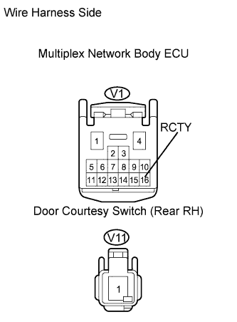 |
Check the wire harness between the multiplex network body ECU and door courtesy switch (rear RH).
Disconnect the V1 ECU connector.
Disconnect the V11 switch connector.
Measure the resistance of the wire harness side connectors.
| Tester Connection | Specified Condition |
| V1-16 (RCTY) - V11-1 | Below 1 Ω |
| V1-16 (RCTY) or V11-1 - Body ground | 10 kΩ or higher |
|
| ||||
| OK | ||
| ||
