NAVIGATION SYSTEM > Television Camera ECU Power Source Circuit |
| 1.INSPECT FUSE (TV, ECU-IG LH, ACC) |
Remove the TV and ECU-IG LH fuses from the cowl side junction block LH.
Remove the ACC fuse from the cowl side junction block RH.
Measure the resistance of the fuses.
|
| ||||
| OK | |
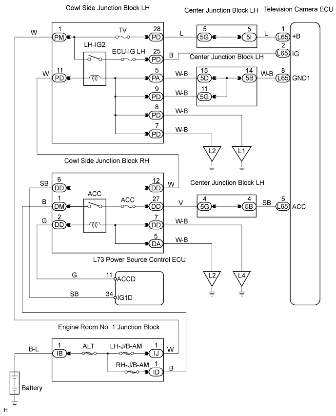
| 2.CHECK TELEVISION CAMERA ECU (+B, ACC, IG TERMINAL) |
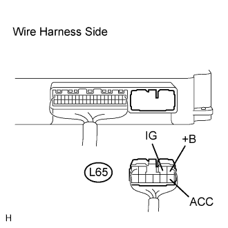 |
Disconnect the L65 ECU connector.
Measure the voltage of the wire harness side connector.
| Tester Connection | Condition | Specified Condition |
| L65-1 (+B) - Body ground | Always | 10 to 14 V |
| L65-5 (ACC) - Body ground | Engine switch on (ACC) | 10 to 14 V |
| L65-2 (IG) - Body ground | Engine switch on (IG) | 10 to 14 V |
|
| ||||
| OK | |
| 3.CHECK WIRE HARNESS (TELEVISION CAMERA ECU - BODY GROUND) |
 |
Disconnect the L65 ECU connector.
Measure the resistance of the wire harness side connector.
| Tester Connection | Condition | Specified Condition |
| L65-8 (GND1) - Body ground | Always | Below 1 Ω |
|
| ||||
| OK | ||
| ||
