NAVIGATION SYSTEM > AVC-LAN Circuit between Radio Receiver and AMP |

| 1.INSPECT RADIO RECEIVER ASSEMBLY |
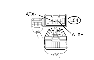 |
Disconnect the L54 receiver connector.
Measure the resistance of the receiver.
| Tester Connection | Condition | Specified Condition |
| L54-5 (ATX+) - L54-15 (ATX-) | Always | 60 to 80 Ω |
|
| ||||
| OK | |
| 2.CHECK WIRE HARNESS (RADIO RECEIVER ASSEMBLY - STEREO COMPONENT AMPLIFIER) |
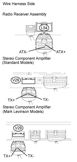 |
Disconnect the L54 receiver connector.
Disconnect the V29 amplifier connector.
Measure the resistance of the wire harness side connectors.
| Tester Connection | Condition | Specified Condition |
| L54-5 (ATX+) - V29-8 (TX+) | Always | Below 1 Ω |
| L54-15 (ATX-) - V29-7 (TX-) | Always | Below 1 Ω |
| L54-5 (ATX+) - Body ground | Always | 10 kΩ or higher |
| L54-15 (ATX-) - Body ground | Always | 10 kΩ or higher |
|
| ||||
| OK | ||
| ||
