LIGHTING SYSTEM > Hazard Warning Switch Circuit |
| 1.INSPECT MULTI-DISPLAY (HAZARD WARNING SWITCH) |
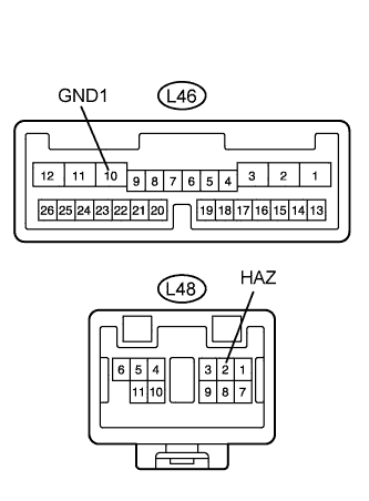 |
Disconnect theL46 and L48 display connectors.
Measure the resistance of the wire harness side connectors.
| Tester Connection | Condition | Specified Condition |
| L48-2 (HAZ) - L46-10 (GND1) | Hazard warning switch OFF | 10 kΩ or higher |
| L48-2 (HAZ) - L46-10 (GND1) | Hazard warning switch ON | Below 1 Ω |
|
| ||||
| OK | |
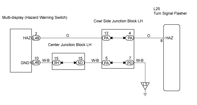
| 2.CHECK WIRE HARNESS (MULTI-DISPLAY (HAZARD WARNING SWITCH) - TURN SIGNAL FLASHER AND BODY GROUND) |
 |
Disconnect the L46 and L48 display connectors.
Disconnect the L25 flasher connector.
Measure the resistance of the wire harness side connectors.
| Tester Connection | Specified Condition |
| L48-2 (HAZ) - L25-8 (HAZ) | Below 1 Ω |
| L48-2 (HAZ) or L25-8 (HAZ) - Body ground | 10 kΩ or higher |
| L46-10 (GND1) - Body ground | Below 1 Ω |
|
| ||||
| OK | ||
| ||
