LIGHTING SYSTEM > Luggage Room Light Circuit |
| 1.PERFORM ACTIVE TEST BY INTELLIGENT TESTER |
Select the Active Test, use the intelligent tester to generate a control command, and then check that the room light (luggage) illuminates.
| Item | Test Details | Diagnostic Note |
| Luggage Light control | Luggage light control ON / OFF | - |
|
| ||||
| NG | ||
| ||
| 2.INSPECT FUSE (RR-B) |
Remove the RR-B fuse from the No. 1 junction block assembly.
Measure the resistance of the fuse.
|
| ||||
| OK | |
| 3.REPLACE ROOM LIGHT (LUGGAGE) |
Temporarily replace the room light (luggage) with a new or normally functioning one.
Turn the room light switch ON.
Check that the light illuminates.
|
| ||||
| NG | |
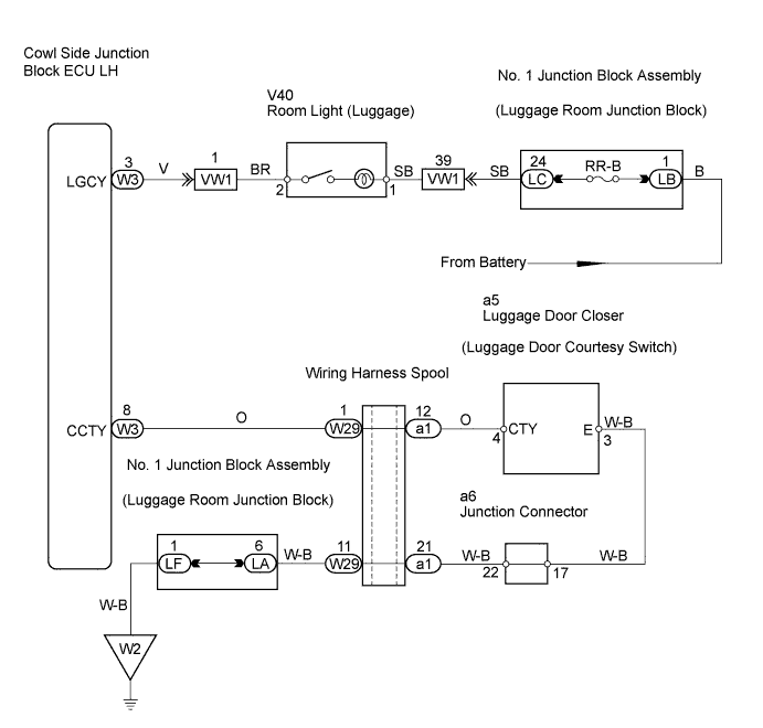
| 4.CHECK WIRE HARNESS (COWL SIDE JUNCTION BLOCK ECU LH - BATTERY) |
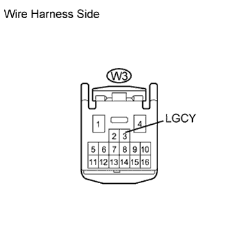 |
Disconnect the W3 ECU connector.
Measure the voltage of the wire harness side connector.
| Tester Connection | Condition | Specified Condition |
| W3-3 (LGCY) - Body ground | Room light switch ON | 10 to 14 V |
| W3-3 (LGCY) - Body ground | Room light switch OFF | 0 V |
|
| ||||
| OK | |
| 5.INSPECT LUGGAGE DOOR CLOSER (LUGGAGE DOOR COURTESY SWITCH) |
|
| ||||
| OK | |
| 6.CHECK WIRE HARNESS (COWL SIDE JUNCTION BLOCK ECU LH - LUGGAGE DOOR CLOSER - BODY GROUND) |
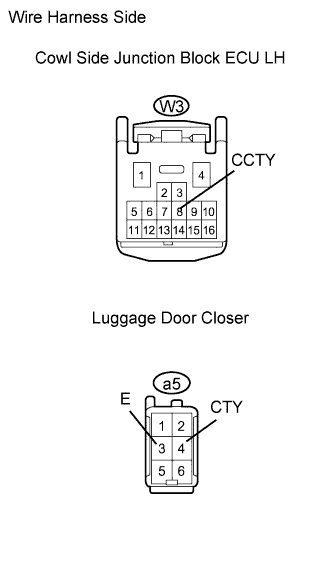 |
Disconnect the W3 ECU connector.
Disconnect the a5 closer connector.
Measure the resistance of the wire harness side connectors.
| Tester Connection | Specified Condition |
| W3-8 (CCTY) - a5-4 (CTY) | Below 1 Ω |
| W3-8 (CCTY) or a5-4 (CTY) - Body ground | 10 kΩ or higher |
| a5-3 (E) - Body ground | Below 1 Ω |
|
| ||||
| OK | ||
| ||
