LIGHTING SYSTEM > Headlight Beam Level Control Actuator Circuit |
| 1.CHECK WIRE HARNESS (AFS ECU - HEADLIGHT) |
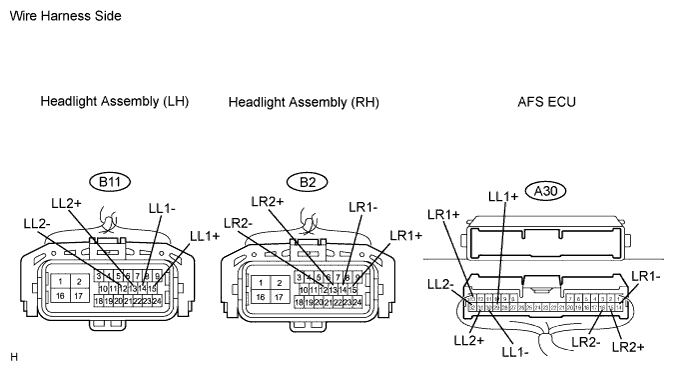
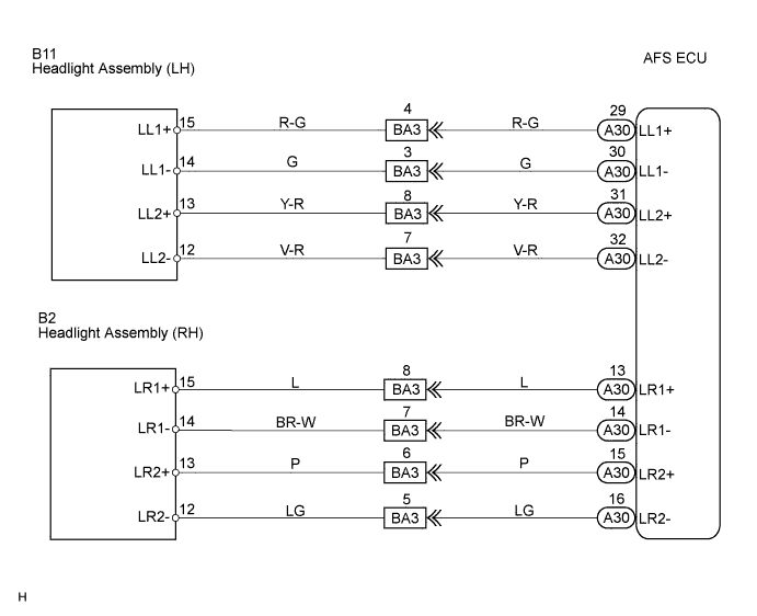
Disconnect the headlight connector on the headlight beam level control motor side and headlight beam level control ECU connector.
Measure the resistance of the wire harness side connectors.
| Tester Connection | Condition | Specified Condition |
| A30-29 (LL1+) - B11-15 (LL1+) | Always | Below 1 Ω |
| A30-30 (LL1-) - B11-14 (LL1-) | Always | Below 1 Ω |
| A30-31 (LL2+) - B11-13 (LL2+) | Always | Below 1 Ω |
| A30-32 (LL2-) - B11-12 (LL2-) | Always | Below 1 Ω |
| A30-29 (LL1+) or B11-15 (LL1+) - Body ground | Always | 10 kΩ or higher |
| A30-30 (LL1-) or B11-14 (LL1-) - Body ground | Always | 10 kΩ or higher |
| A30-31 (LL2+) or B11-13 (LL2+) - Body ground | Always | 10 kΩ or higher |
| A30-32 (LL2-) or B11-12 (LL2-) - Body ground | Always | 10 kΩ or higher |
| Tester Connection | Condition | Specified Condition |
| A30-13 (LR1+) - B2-15 (LR1+) | Always | Below 1 Ω |
| A30-14 (LR1-) - B2-14 (LR1-) | Always | Below 1 Ω |
| A30-15 (LR2+) - B2-13 (LR2+) | Always | Below 1 Ω |
| A30-16 (LR2-) - B2-12 (LR2-) | Always | Below 1 Ω |
| A30-13 (LR1+) or B2-15 (LR1+) - Body ground | Always | 10 kΩ or higher |
| A30-14 (LR1-) or B2-14 (LR1-) - Body ground | Always | 10 kΩ or higher |
| A30-15 (LR2+) or B2-13 (LR2+) - Body ground | Always | 10 kΩ or higher |
| A30-16 (LR2-) or B2-12 (LR2-) - Body ground | Always | 10 kΩ or higher |
|
| ||||
| OK | |
| 2.INSPECT HEADLIGHT BEAM LEVEL CONTROL MOTOR |
 |
Measure the resistance of the motor.
| Tester Connection | Condition | Specified Condition |
| 1 - 2 | Always | 5.8 to 12.5 Ω |
| 3 - 4 | Always | 5.8 to 12.5 Ω |
|
| ||||
| OK | ||
| ||
