LIGHTING SYSTEM > Room Light Circuit |

| 1.PERFORM ACTIVE TEST BY INTELLIGENT TESTER |
Select the Active Test, use the intelligent tester to generate a control command, and then check that the room light illuminates.
| Item | Test Details | Diagnostic Note |
| Seat Light operation | Seat light operation ON / OFF | - |
| Shift Light operation | Shift light operation ON / OFF | - |
|
| ||||
| OK | ||
| ||
| 2.CHECK WIRE HARNESS (COWL SIDE JUNCTION BLOCK ECU LH - MAP LIGHT ASSEMBLY) |
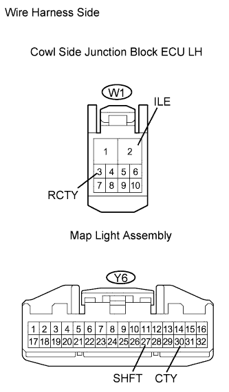 |
Disconnect the W1 junction block connector.
Disconnect the Y6 overhead junction block connector.
Measure the resistance of the wire harness side connectors.
| Tester Connection | Specified Condition |
| W1-3 (RCTY) - Y6-27 (SHFT) | Below 1 Ω |
| W1-2 (ILE) - Y6-30 (CTY) | Below 1 Ω |
| W1-3 (RCTY) or Y6-27 (SHFT) - Body ground | 10 kΩ or higher |
| W1-2 (ILE) or Y6-30 (CTY) - Body ground | 10 kΩ or higher |
|
| ||||
| OK | |
| 3.INSPECT FUSE (DOME, D/C CUT) |
Remove the DOME and D/C CUT fuses from the engine room No. 1 relay block.
Measure the resistance of the fuses.
|
| ||||
| OK | |
| 4.CHECK WIRE HARNESS (MAP LIGHT ASSEMBLY - BATTERY) |
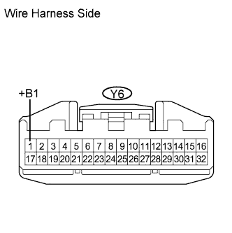 |
Disconnect the Y6 map light connector.
Measure the voltage of the wire harness side connector.
| Tester Connection | Specified Condition |
| Y6-1 (+B1) - Body ground | 10 to 14 V |
|
| ||||
| OK | |
| 5.CHECK WIRE HARNESS (MAP LIGHT ASSEMBLY - BODY GROUND) |
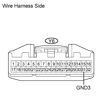 |
Disconnect the Y6 map light connector.
Measure the resistance of the wire harness side connectors.
| Tester Connection | Specified Condition |
| Y6-31 (GND3) - Body ground | Below 1 Ω |
|
| ||||
| OK | |
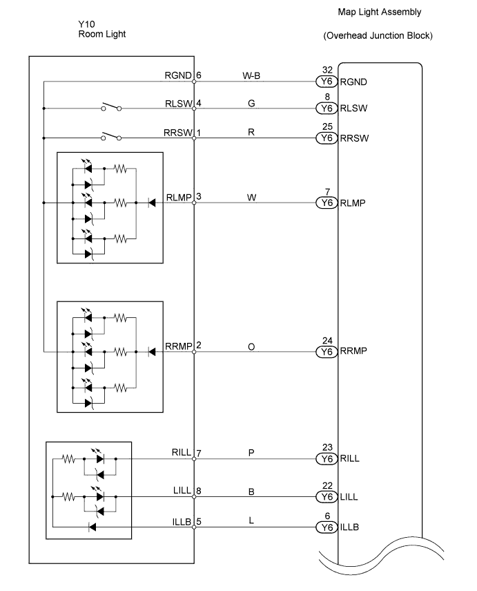
| 6.CHECK WIRE HARNESS (MAP LIGHT ASSEMBLY - ROOM LIGHT) |
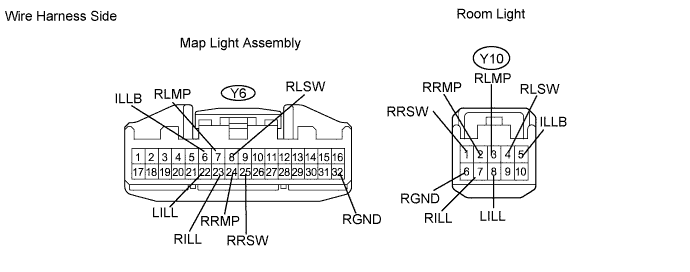
Disconnect the Y6 map light connector.
Disconnect the Y10 room light connector.
Measure the resistance of the wire harness side connectors.
| Tester Connection | Specified Condition |
| Y6-32 (RGND) - Y10-6 (RGND) | Below 1 Ω |
| Y6-8 (RLSW) - Y10-4 (RLSW) | Below 1 Ω |
| Y6-25 (RRSW) - Y10-1 (RRSW) | Below 1 Ω |
| Y6-7 (RLMP) - Y10-3 (RLMP) | Below 1 Ω |
| Y6-24 (RRMP) - Y10-2 (RRMP) | Below 1 Ω |
| Y6-23 (RILL) - Y10-7 (RILL) | Below 1 Ω |
| Y6-22 (LILL) - Y10-8 (LILL) | Below 1 Ω |
| Y6-6 (ILLB) - Y10-5 (ILLB) | Below 1 Ω |
| Y6-32 (RGND) or Y10-6 (RGND) - Body ground | 10 kΩ or higher |
| Y6-8 (RLSW) or Y10-4 (RLSW) - Body ground | 10 kΩ or higher |
| Y6-25 (RRSW) or Y10-1 (RRSW) - Body ground | 10 kΩ or higher |
| Y6-7 (RLMP) or Y10-3 (RLMP) - Body ground | 10 kΩ or higher |
| Y6-24 (RRMP) or Y10-2 (RRMP) - Body ground | 10 kΩ or higher |
| Y6-23 (RILL) or Y10-7 (RILL) - Body ground | 10 kΩ or higher |
| Y6-22 (LILL) or Y10-8 (LILL) - Body ground | 10 kΩ or higher |
| Y6-6 (ILLB) or Y10-5 (ILLB) - Body ground | 10 kΩ or higher |
|
| ||||
| OK | |
| 7.REPLACE ROOM LIGHT |
Temporarily replace the room light with a new or normally functioning one.
Check that the light illuminates.
|
| ||||
| NG | ||
| ||
