LIGHTING SYSTEM > Headlight Signal Circuit |
| 1.CHECK WIRE HARNESS (MULTIPLEX NETWORK BODY ECU - BODY GROUND) |
 |
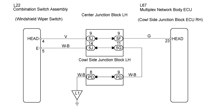
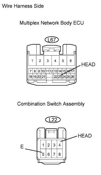
Measure the voltage of the wire harness side connector.
| Tester Connection | Specified Condition |
| L67-23 (HEAD) - Body ground | 10 to 14 V |
|
| ||||
| NG | ||
| ||
| 2.CHECK WIRE HARNESS (MULTIPLEX NETWORK BODY ECU - SWITCH - BODY GROUND) |
 |
Disconnect the L67 ECU connector.
Disconnect the L22 switch connector.
Measure the resistance of the wire harness side connectors.
| Tester Connection | Specified Condition |
| L67-23 (HEAD) - L22-4 (HEAD) | Below 1 Ω |
| L67-23 (HEAD) or L22-4 (HEAD) - Body ground | 10 kΩ or higher |
| L22-5 (E) - Body ground | Below 1 Ω |
|
| ||||
| OK | ||
| ||
