LIGHTING SYSTEM > Step Illumination Circuit |
| 1.CHECK OPERATION OF FOOT LIGHT |
When a door is opened, check that the appropriate light illuminates.
| Result | Proceed to |
| All lights do not illuminate | A |
| Foot light (LH) does not illuminate | B |
| Foot light (RH) does not illuminate | C |
| Foot light (Rear LH) does not illuminate | D |
| Foot light (Rear RH) does not illuminate | E |
|
| ||||
|
| ||||
|
| ||||
|
| ||||
| A | |
| 2.PERFORM ACTIVE TEST BY INTELLIGENT TESTER |
Select the Active Test, use the intelligent tester to generate a control command, and then check that the step light illuminates.
| Item | Test Details | Diagnostic Note |
| Step Light Operation | Step light operation ON / OFF | - |
|
| ||||
| OK | ||
| ||
| 3.INSPECT FUSE (DOME, D/C CUT) |
Remove the DOME fuse from the engine room No. 1 relay block.
Remove the D/C CUT fuse from the engine room No. 1 relay block.
Measure the resistance of the fuses.
|
| ||||
| OK | ||
| ||
| 4.REPLACE FOOT LIGHT (LH) |
Temporarily replace the foot light (LH) with a new or normally functioning one.
Check that the foot light illuminates.
|
| ||||
| NG | |
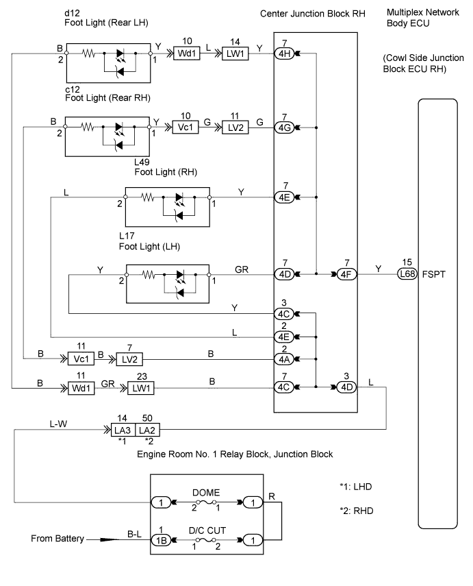
| 5.CHECK WIRE HARNESS (FOOT LIGHT (LH) - BATTERY) |
 |
Disconnect the L17 light connector.
Measure the voltage of the wire harness side connector.
| Tester Connection | Specified Condition |
| L17-2 - Body ground | 10 to 14 V |
|
| ||||
| OK | |
| 6.CHECK WIRE HARNESS (FOOT LIGHT (LH) - MULTIPLEX NETWORK BODY ECU) |
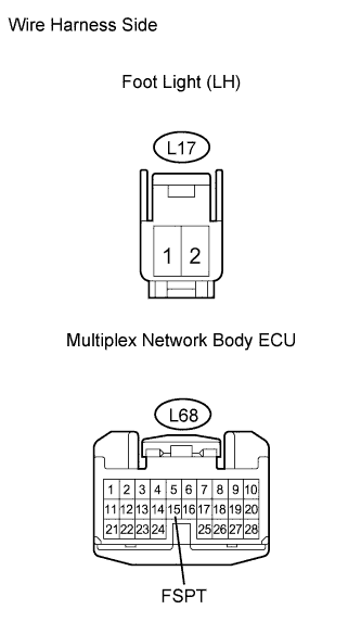 |
Disconnect the L17 light connector.
Disconnect the L68 ECU connector.
Measure the resistance of the wire harness side connector.
| Tester Connection | Specified Condition |
| L17-1 - L68-15 (FSPT) | Below 1 Ω |
| L17-1 or L68-15 (FSPT) - Body ground | 10 kΩ or higher |
|
| ||||
| OK | ||
| ||
| 7.REPLACE FOOT LIGHT (RH) |
Temporarily replace the foot light (RH) with a new or normally functioning one.
Check that the foot light illuminates.
|
| ||||
| NG | |
| 8.CHECK WIRE HARNESS (FOOT LIGHT (RH) - BATTERY) |
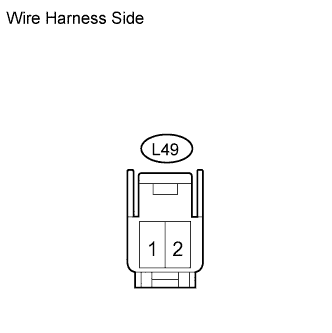 |
Disconnect the L49 light connector.
Measure the voltage of the wire harness side connector.
| Tester Connection | Specified Condition |
| L49-2 - Body ground | 10 to 14 V |
|
| ||||
| OK | |
| 9.CHECK WIRE HARNESS (FOOT LIGHT (RH) - MULTIPLEX NETWORK BODY ECU) |
 |
Disconnect the L49 light connector.
Disconnect the L68 ECU connector.
Measure the resistance of the wire harness side connectors.
| Tester Connection | Specified Condition |
| L49-1 - L68-15 (FSPT) | Below 1 Ω |
| L49-1 or L68-15 (FSPT) - Body ground | 10 kΩ or higher |
|
| ||||
| OK | ||
| ||
| 10.REPLACE FOOT LIGHT (REAR LH) |
Temporarily replace the foot light (rear LH) with a new or normally functioning one.
Check that the foot light illuminates.
|
| ||||
| NG | |
| 11.CHECK WIRE HARNESS (FOOT LIGHT (REAR LH) - BATTERY) |
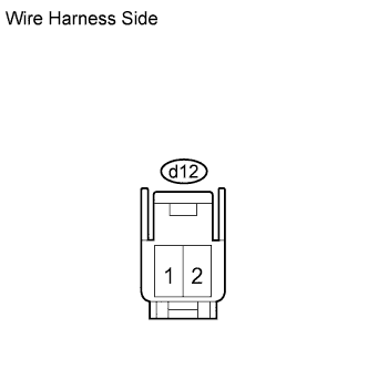 |
Disconnect the d12 light connector.
Measure the voltage of the wire harness side connector.
| Tester Connection | Specified Condition |
| d12-2 - Body ground | 10 to 14 V |
|
| ||||
| OK | |
| 12.CHECK WIRE HARNESS (FOOT LIGHT (REAR LH) - MULTIPLEX NETWORK BODY ECU) |
 |
Disconnect the d12 light connector.
Disconnect the L68 ECU connector.
Measure the resistance of the wire harness side connectors.
| Tester Connection | Specified Condition |
| d12-1 - L68-15 (FSPT) | Below 1 Ω |
| d12-1 or L68-15 (FSPT) - Body ground | 10 kΩ or higher |
|
| ||||
| OK | ||
| ||
| 13.REPLACE FOOT LIGHT (REAR RH) |
Temporarily replace the foot light (rear RH) with a new or normally functioning one.
Check that the foot light illuminates.
|
| ||||
| NG | |
| 14.CHECK WIRE HARNESS (FOOT LIGHT (REAR RH) - BATTERY) |
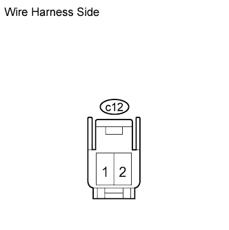 |
Disconnect the c12 light connector.
Measure the voltage of the wire harness side connector.
| Tester Connection | Specified Condition |
| c12-2 - Body ground | 10 to 14 V |
|
| ||||
| OK | |
| 15.CHECK WIRE HARNESS (FOOT LIGHT (REAR RH) - MULTIPLEX NETWORK BODY ECU) |
 |
Disconnect the c12 light connector.
Disconnect the L68 ECU connector.
Measure the resistance of the wire harness side connectors.
| Tester Connection | Specified Condition |
| c12-1 - L68-15 (FSPT) | Below 1 Ω |
| c12-1 or L68-15 (FSPT) - Body ground | 10 kΩ or higher |
|
| ||||
| OK | ||
| ||
