WINDSHIELD GLASS > INSTALLATION |
| 1. INSTALL WINDSHIELD GLASS SPACER |

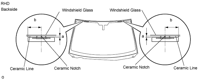
| Area | Measurement |
| a | 4.4 mm (0.173 in.) |
| b | 40.0 mm (1.574 in.) |
Apply Primer G to the glass where the spacers will be installed.
Install 2 new spacers onto the glass as shown in the illustration.
| 2. INSTALL WINDSHIELD GLASS RETAINER |


| Area | Measurement |
| a | 30 mm (1.181 in.) |
Apply Primer G to the glass where the retainer will be installed.
Install 2 new retainers onto the glass as shown in the illustration.
| 3. INSTALL NO. 1 WINDSHIELD GLASS STOPPER |
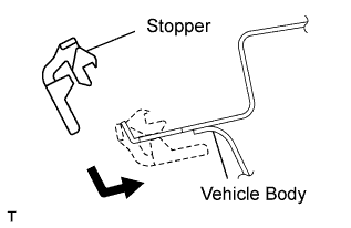 |
Install 2 new stoppers to the vehicle body as shown in the illustration.
| 4. INSTALL WINDSHIELD GLASS ADHESIVE DAM |
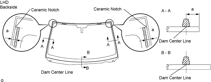
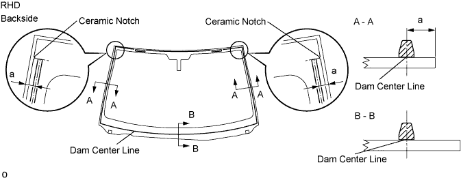
| Area | Measurement |
| a | 9.5 mm (0.374 in.) |
Apply Primer G to the glass where the glass adhesive dams will be installed.
Remove the peeling paper from the adhesive part of the dam. Install the dam (adhesive side) to the glass (Primer G area), but exclude the area above the notches on the upper part of the glass.
| 5. INSTALL WINDSHIELD GLASS |
 |
Position the glass.
Using suction cups, place the glass in the correct position.
Check that the entire contact surface of the glass rim is perfectly even.
Place matchmarks on the glass and vehicle body on the locations indicated in the illustration.
Using suction cups, remove the glass.
 |
Using a brush, apply Primer M to the exposed part of the vehicle body.
Using a brush or sponge, apply Primer G to the contact surface of the glass.
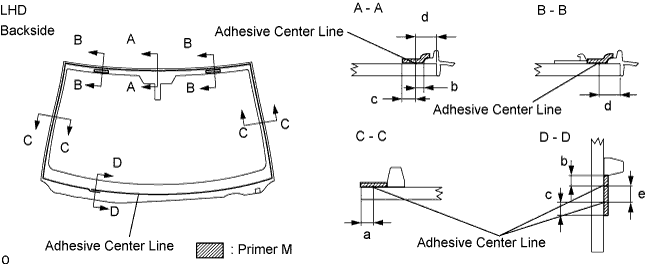

| Area | Measurement |
| a | 3.0 mm (0.118 in.) |
| b | 4.0 mm (0.157 in.) |
| c | 7.0 mm (0.276 in.) |
| d | 7.5 mm (0.295 in.) |
| e | 8.0 mm (0.315 in.) |
Apply adhesive to the glass.
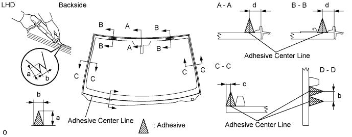
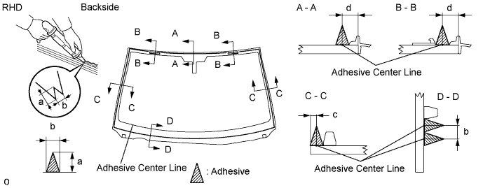
| Area | Measurement |
| a | 12.0 mm (0.472 in.) |
| b | 8.0 mm (0.315 in.) |
| c | 3.0 mm (0.118 in.) |
| d | 7.5 mm (0.295 in.) |
Cut off the tip of the cartridge nozzle as shown in the illustration.
| Temperature | Usage Timeframe |
| 35°C (95°F) | 15 minutes |
| 20°C (68°F) | 1 hour 40 minutes |
| 5°C (41°F) | 8 hours |
Load the sealer gun with the cartridge.
Apply adhesive to the glass as shown in the illustration.
 |
Install the glass to the vehicle body.
Using suction cups, position the glass so that the matchmarks are aligned. Press it in gently along the rim.
Lightly press the outer surface of the glass to ensure that it is securely fit to the vehicle body.
Hold the glass in place securely with protective tape or equivalent until the adhesive hardens.
| Temperature | Minimum time prior to driving vehicle |
| 35°C (95°F) | 1 hour 30 minutes |
| 20°C (68°F) | 5 hours |
| 5°C (41°F) | 24 hours |
| 6. INSTALL RAIN SENSOR (w/ RAIN SENSOR) |
If reusing the rain sensor:
Install new rain sensor tape.
Remove the used rain sensor tape from the windshield glass or rain sensor.
 |
Apply new rain sensor tape on the rain sensor lens surface, indicated by the hatched area.
| Area | Measurement |
| A | 7.5 mm (0.295 in.) |
| B | 24.7 mm (0.972 in.) |
| C | 13.5 mm (0.531 in.) |
Install the rain sensor.
Peel the separation paper from the rain sensor tape.
 |
Securely attach the rain sensor to the bracket.
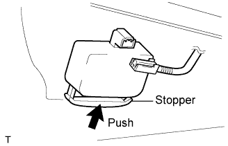 |
Push the stopper upward.
Connect the connector.
| 7. INSTALL INNER REAR VIEW MIRROR ASSEMBLY |
 |
Connect the connector.
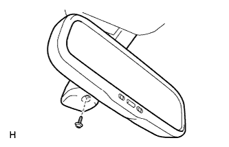 |
Install the mirror with the screw.
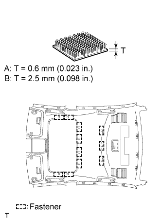
| 8. INSTALL ROOF HEADLINING ASSEMBLY |
 |
Apply double-sided tape to the pads.
Align the pads with the markings on the roof headlining, and then install the pads.
 |
Only when replacing the sliding roof housing:
Remove the 11 fasteners from the removed sliding roof housing, and attach them to the roof headlining.
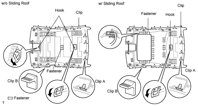
Place the roof headlining in the vehicle through the rear door.
w/o Sliding roof:
Attach the 2 hooks and 4 clips to the vehicle body.
w/ Sliding roof:
Attach the hook, claw and 4 clips to the vehicle body.
Only when replacing the roof headlining:
Remove the 11 fasteners from the removed roof headlining, and attach them to the new roof headlining.
Attach the clips on the rear side of the vehicle.
w/ Sliding roof:
Install the roof headlining to the sliding roof housing.
Attach the clamp of the roof wire to the front pillar garnish LH. Then connect the connector.
w/ Sliding roof:
| 9. INSTALL ASSIST GRIP ASSEMBLY |
| 10. INSTALL VANITY LIGHT ASSEMBLY |
| 11. INSTALL STEERING SPOT LIGHT ASSEMBLY |
Connect the connector.
Attach the 2 claws to install the spot light.
| 12. INSTALL PERSONAL LIGHT ASSEMBLY |
Connect the connector.
Attach the 3 claws and 2 clips, and install the personal light.
Install the 2 screws and 2 covers to the personal light.
| 13. INSTALL INNER REAR MIRROR COVER |
| 14. INSTALL FRONT ROOF TOP GARNISH |
Attach the 3 claws and 2 clips, and install the top garnish.
| 15. INSTALL VISOR HOLDER |
| 16. INSTALL VISOR ASSEMBLY LH |
Install the visor with the 2 screws.
| 17. INSTALL VISOR ASSEMBLY RH |
Install the visor with the 2 screws.
| 18. INSTALL VISOR BRACKET COVER |
Attach the 4 claws to install the cover.
| 19. INSTALL FRONT PILLAR GARNISH LH |
 |
Attach a new clip A to the vehicle body.
Set the pillar garnish to the area labeled B. Using needle-nose pliers, install clip A to the pillar garnish and rotate it 90°.
Install the pillar garnish by attaching the claws and clip.
Pull out the folded lip of the weatherstrip.
| 20. INSTALL FRONT PILLAR GARNISH RH |
| 21. INSTALL FRONT DOOR OPENING TRIM COVER LH |
Attach the 3 claws to install the trim cover.
Pull out the folded lip of the weatherstrip.
| 22. INSTALL FRONT DOOR OPENING TRIM COVER RH |
| 23. INSTALL FRONT DOOR SCUFF PLATE LH |
 |
Attach the 5 claws to install the scuff plate.
Pull out the folded lip of the weatherstrip.
| 24. INSTALL FRONT DOOR SCUFF PLATE RH |
| 25. INSTALL ROOF DRIP SIDE FINISH MOULDING CLIP |

Remove the tape that remains on the moulding installation area of the vehicle body, and then clean the surface with white gasoline.
Heat the clip installation surfaces of the vehicle body and the installation part of the clips.
Install new clips in the positions shown in the illustration. Press-fit the clips by hand.
| 26. INSTALL ROOF DRIP SIDE FINISH MOULDING CENTER LH |
 |
Install the moulding to the vehicle body's 16 clips.
Remove the protective tape from the edges of the moulding.
| 27. INSTALL ROOF DRIP SIDE FINISH MOULDING CENTER RH |
|
Install the moulding to the vehicle body's 16 clips.
Remove the protective tape from the edges of the moulding.
| 28. INSTALL COWL TOP VENTILATOR LOUVER SUB-ASSEMBLY |
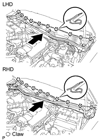 |
Push the ventilator louver in the direction indicated by the arrow in the illustration. Attach the 10 claws to install the ventilator louver.
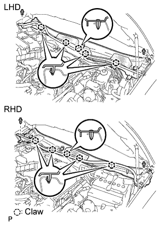 |
Attach the 5 claws and 2 clips to install the ventilator louver.
| 29. INSTALL FRONT WIPER ARM LH |
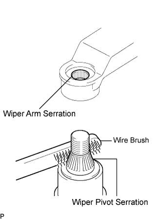 |
Stop the wiper motor at the automatic stop position.
Clean the wiper arm serration with a round file or equivalent.
Clean the wiper pivot serration with a wire brush.
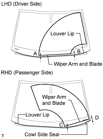 |
Install the wiper arm and blade with the nut. Make sure that the wiper arm and blade comes to the position shown in the illustration.
| Area | Measurement |
| A (for LHD) | 25.3 mm (0.996 in.) |
| B (for LHD) | 26.2 mm (1.031 in.) |
| C (for RHD) | 21.8 mm (0.858 in.) |
| D (for RHD) | 28.9 mm (1.138 in.) |
| 30. INSTALL FRONT WIPER ARM RH |
|
Stop the wiper motor at the automatic stop position.
Clean the wiper arm serration with a round file or equivalent.
Clean the wiper pivot serration with a wire brush.
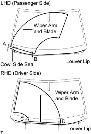 |
Install the wiper arm and blade with the nut. Make sure that the wiper arm and blade comes to the position shown in the illustration.
| Area | Measurement |
| A (for LHD) | 28.9 mm (1.138 in.) |
| B (for LHD) | 21.8 mm (0.858 in.) |
| C (for RHD) | 26.2 mm (1.031 in.) |
| D (for RHD) | 25.3 mm (0.996 in.) |
Operate the front wipers while spraying washer fluid on the windshield glass. Make sure that the front wipers function properly and there is no interference with the vehicle body.
| 31. INSTALL FRONT FENDER TO COWL SIDE SEAL LH |
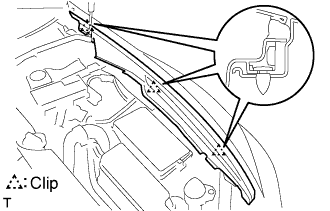 |
Attach the 3 clips to install the side seal.
| 32. INSTALL FRONT FENDER TO COWL SIDE SEAL RH |
| 33. INSTALL ENGINE ROOM SIDE COVER LH (for LHD) |
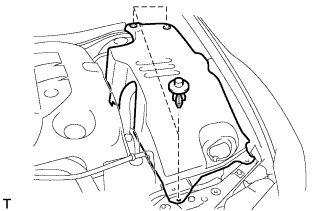 |
Install the side cover with the 3 clips.
| 34. INSTALL ENGINE ROOM SIDE COVER RH (for RHD) |
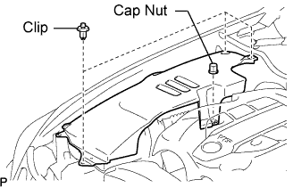 |
Install the side cover with the 3 clips and cap nut.
| 35. INSTALL COOL AIR INTAKE DUCT SEAL |
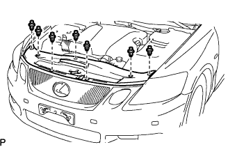 |
Install the duct seal with the 7 clips.
| 36. CHECK FOR LEAKS AND REPAIR |
Conduct a leak test after the adhesive has completely hardened.
Seal any leaks with auto glass sealer.
| 37. CONNECT CABLE TO NEGATIVE BATTERY TERMINAL |
| 38. PERFORM INITIALIZATION |
Perform initialization (Click here).
