PARKING BRAKE PEDAL (for LHD) > INSTALLATION |
| 1. INSTALL PARKING BRAKE PEDAL |
 |
Temporarily install the parking brake pedal by loosely tightening the 3 nuts.
Fully tighten the 3 nuts in the order shown in the illustration.
Connect the connector.
 |
Install the instrument panel junction block assembly with the 2 nuts.
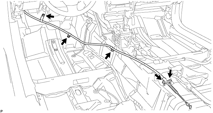
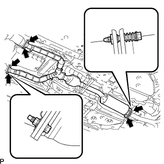
Install the parking brake No.1 cable assembly to the body with the 3 nuts and 2 bolts.
 |
Install the parking brake equalizer to the parking brake No.1 cable assembly.
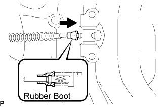 |
Slide the rubber boot back as shown in the illustration.
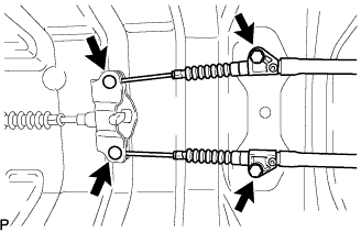 |
Connect the parking brake No.2 and No.3 cable assemblies to the parking brake equalizer.
Install the parking brake No.2 and No.3 cable assemblies with the 2 bolts.
 |
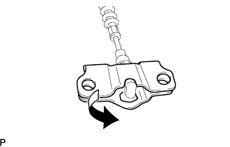
Using needle-nose pliers, install the parking brake return with damper spring.
| 2. INSTALL FRONT FLOOR REAR UPPER SUB PANEL |
 |
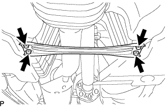
Install the front floor rear upper sub panel with the 4 bolts.
Engage the clamps.
| 3. INSTALL CENTER AIRBAG SENSOR ASSEMBLY |
Check that the engine switch is off.
Check that the battery negative (-) terminal is disconnected.
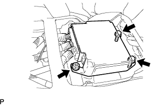 |
Install the center airbag sensor with the nut and 2 bolts.
Check that there is no looseness in the installation parts of the center airbag sensor.
Connect the holder (with connectors).
Check that the water-proof sheet is properly set.
| 4. INSTALL DASH PANEL INSULATOR NO.3 PAD |
| 5. INSTALL REAR PROPELLER SHAFT ASSEMBLY (for 3GR-FSE) |
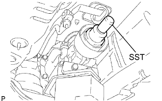 |
Remove the SST from the transmission.
Insert the yoke of the intermediate shaft into the transmission.
 |
Install the 2 center support bearing washers and center support bearing, and temporarily tighten the 2 bolts.
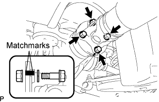 |
Align the matchmarks on the propeller shaft flange and differential companion flange, and connect the shaft with the 4 bolts, washers and nuts.
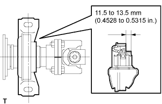 |
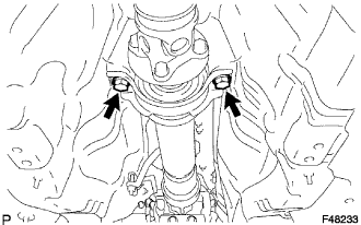
Adjust the dimension between the edge surface of the center support bearing and the edge surface of the cushion to 11.5 to 13.5 mm (0.4528 to 0.5315 in.) respectively as shown in illustration.
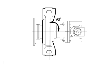 |
Check that the center line of the bracket is at right angles to the shaft axial direction.
|
Tighten the 2 bolts.
| 6. INSPECT AND ADJUST NO. 2 AND NO. 3 JOINT ANGLE (for 3GR-FSE) |
Stabilize the propeller shaft and differential.
Turn the propeller shaft several times by hand to stabilize the center support bearing.
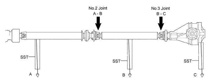
Check the No.2 and No.3 joint angles.
Using SST, measure the installation angle of the intermediate shaft and propeller shaft.
Using SST, measure the installation angle of the differential.
Calculate the No.2 joint angle.
Calculate the No.3 joint angle.
Adjust the No.2 joint angle .
Select the center support bearing washers for adjustment.
| Thickness mm (in.) |
| 2 (0.078) |
| 4.5 (0.1772) |
| 6.5 (0.2559) |
| 9.0 (0.3543) |
| 11 (0.4331) |
| 13.5 (0.5315) |
| 7. INSTALL FRONT FLOOR HEAT NO.1 INSULATOR (for 3GR-FSE) |
Install the heat insulator No.1 with the 4 nuts and grommet.
| 8. INSTALL FRONT EXHAUST PIPE ASSEMBLY (for 3GR-FSE) |
 |
Using a vernier caliper, measure the free length of the compression spring.
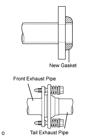 |
Install a new gasket to the rear side of the front exhaust pipe.
 |
Install 2 new gaskets and the exhaust pipe front ends to the exhaust manifold with the 4 bolts and 2 nuts.
Install the front exhaust pipe to the tailpipe with the 2 compression springs and 2 bolts.
| 9. INSTALL HEATED OXYGEN SENSOR (for 3GR-FSE) |
Install the 2 sensors (Click here).
| 10. INSTALL FRONT FLOOR BRACE CENTER (for 3GR-FSE) |
 |
Install the floor brace with the 4 bolts.
| 11. INSTALL REAR PROPELLER SHAFT ASSEMBLY (for 3GR-FE) |
|
Remove the SST from the transmission.
Insert the yoke of the intermediate shaft into the transmission.
|
Install the 2 center support bearing washers and center support bearing, and temporarily tighten the 2 bolts.
|
Align the matchmarks on the propeller shaft flange and differential companion flange, and connect the shaft with the 4 bolts, washers and nuts.
|
Adjust the dimension between the edge surface of the center support bearing and the edge surface of the cushion to 11.5 to 13.5 mm (0.4528 to 0.5315 in.) respectively as shown in illustration.
|
Check that the center line of the bracket is at right angles to the shaft axial direction.
|
Tighten the 2 bolts.
| 12. INSPECT AND ADJUST NO. 2 AND NO. 3 JOINT ANGLE (for 3GR-FE) |
Stabilize the propeller shaft and differential.
Turn the propeller shaft several times by hand to stabilize the center support bearing.
Check the No.2 and No.3 joint angles.
Using SST, measure the installation angle of the intermediate shaft and propeller shaft.
Using SST, measure the installation angle of the differential.
Calculate the No.2 joint angle.
Calculate the No.3 joint angle.
Adjust the No.2 joint angle .
Select the center support bearing washers for adjustment.
| Thickness mm (in.) |
| 2 (0.078) |
| 4.5 (0.1772) |
| 6.5 (0.2559) |
| 9.0 (0.3543) |
| 11 (0.4331) |
| 13.5 (0.5315) |
| 13. INSTALL FRONT FLOOR HEAT NO.1 INSULATOR (for 3GR-FE) |
Install the heat insulator No.1 with the 4 nuts and grommet.
| 14. INSTALL FRONT EXHAUST PIPE ASSEMBLY (for 3GR-FE) |
|
Using a vernier caliper, measure the free length of the compression spring.
|
Install a new gasket to the rear side of the front exhaust pipe.
|
Install 2 new gaskets and the exhaust pipe front ends to the exhaust manifold with the 4 bolts and 2 nuts.
Install the front exhaust pipe to the tailpipe with the 2 compression springs and 2 bolts.
| 15. INSTALL HEATED OXYGEN SENSOR (for 3GR-FE) |
Install the 2 sensors (Click here).
| 16. INSTALL FRONT FLOOR BRACE CENTER (for 3GR-FE) |
|
Install the floor brace with the 4 bolts.
| 17. INSTALL REAR PROPELLER SHAFT ASSEMBLY (for 3UZ-FE) |
 |
Apply grease to the flexible coupling centering bushings.
Install the propeller shaft from the vehicle's rear and connect the transmission and differential.
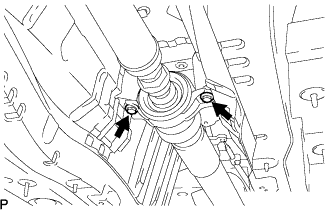 |
Temporarily install the 2 center support bearing set bolts with the adjusting washers.
 |
Align the matchmarks on the transmission companion flange and flexible coupling.
Temporarily install the 3 bolts, washers and nuts.
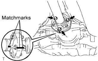 |
Align the matchmarks on the differential companion flange and flexible coupling.
Temporarily install the 3 bolts, washers and nuts.
Tighten the 6 nuts.
| 18. FULLY TIGHTEN CENTER SUPPORT NO.1 BEARING ASSEMBLY (for 3UZ-FE) |
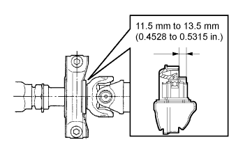 |
Adjust the dimension between the edge surface of the center support bearing and the edge surface of the cushion to 11.5 to 13.5 mm (0.4528 to 0.5315 in.) respectively as shown in illustration.
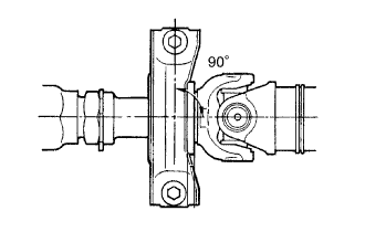 |
Check that the center line of the bracket is at right angles to the shaft axial direction.
|
Tighten the 2 bolts.
 |
Using SST, tighten the adjusting nut.
| 19. INSPECT AND ADJUST NO. 2 AND NO. 3 JOINT ANGLE (for 3UZ-FE) |
Stabilize the propeller shaft and differential.
Turn the propeller shaft several times by hand to stabilize the center support bearing.
Check the No.2 and No.3 joint angles.
Using SST, measure the installation angle of the intermediate shaft and propeller shaft.
Using SST, measure the installation angle of the differential.

Calculate the No.2 joint angle.
Calculate the No.3 joint angle.
Adjust the No.2 joint angle.
Select the center support bearing washers for adjustment.
| thickness mm (in.) |
| 2 (0.0787) |
| 4.5 (0.1772) |
| 6.5 (0.2559) |
| 9.0 (0.3543) |
| 11 (0.4331) |
| 20. INSTALL FRONT FLOOR HEAT NO.1 INSULATOR (for 3UZ-FE) |
Install the heat insulator No.1 with the 4 nuts.
| 21. INSTALL FRONT EXHAUST PIPE ASSEMBLY (for 3UZ-FE) |
|
Using a vernier caliper, measure the free length of the compression spring.
|
Install a new gasket to the rear side of the front exhaust pipe.
 |
Install 2 new gaskets and the 2 TWCs with the 4 bolts.
Install the front exhaust pipe to the tailpipe with the 2 compression springs and 2 bolts.
| 22. INSTALL REAR NO.1 FLOOR PANEL BRACE (for 3UZ-FE) |
 |
Install the panel brace with the 4 bolts.
| 23. INSTALL FRONT FLOOR BRACE CENTER (for 3UZ-FE) |
 |
Install the floor brace with the 4 bolts.
| 24. INSTALL AIR NO.2 DUCT REAR |
| 25. INSTALL FRONT FLOOR SILENCER PAD |
| 26. INSTALL ACCELERATOR PEDAL |
| 27. INSTALL DRIVER SIDE KNEE AIRBAG ASSEMBLY |
 |
Connect the connector.
Install the driver side knee airbag assembly with the 4 bolts.
| 28. INSTALL INSTRUMENT PANEL SAFETY NO.1 PAD SUB-ASSEMBLY |
 |
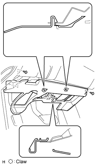
Install the hood lock control cable to the safety pad.
Attach the 8 clips and claw to install the safety pad.
| 29. INSTALL INSTRUMENT PANEL UNDER NO.1 COVER SUB-ASSEMBLY |
 |
Connect the connectors.
Attach the 2 claws to install the under cover.
Install the 2 screws.
| 30. INSTALL INSTRUMENT SIDE PANEL |
 |
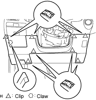
Attach the 2 claws and 4 clips to install the side panel.
| 31. INSTALL CONSOLE BOX |
 |
Connect the connector.
Install the console box with the 4 bolts and 2 screws.
| 32. INSTALL CONSOLE BOX REGISTER ASSEMBLY |
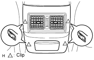 |
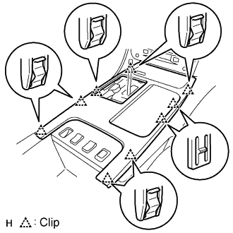
Attach the 4 clips to install the register.
| 33. INSTALL CONSOLE BOX PLATE |
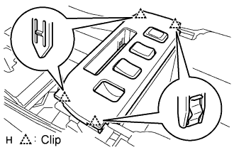 |
Connect the connector.
Attach the 4 clips to install the console box.
| 34. INSTALL INSTRUMENT PANEL FINISH LH PANEL END |
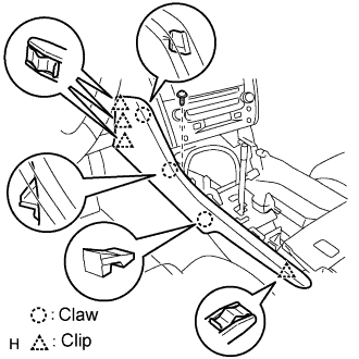 |
Attach the 4 clips and 3 claws to install the finish panel end.
Install the screw.
| 35. INSTALL INSTRUMENT PANEL FINISH RH PANEL END |
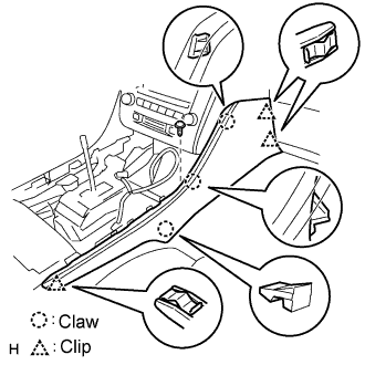 |
Attach the 3 clips and 3 claws to install the finish panel end.
Install the screw.
| 36. INSTALL FRONT ASH RECEPTACLE ASSEMBLY |
 |
Connect the connector.
Attach the 9 clips to install the ash receptacle.
 |
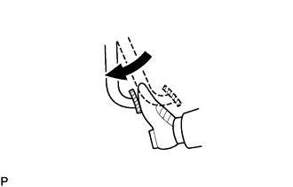
Install the shift lever knob and twist it in the direction indicated by the arrow.
| 37. INSTALL CONSOLE UPPER PANEL GARNISH FRONT |
Attach the claws to install the garnish.
| 38. INSTALL CENTER PILLAR GARNISH LOWER |
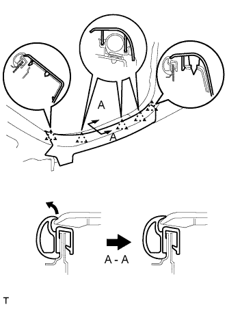
Attach the 2 claws and 5 clips to install the garnish.
Pull out the folded lip of the weatherstrip.
| 39. INSTALL REAR DOOR SCUFF PLATE |
 |
Attach the 5 claws to install the scuff plate.
Pull out the folded lip of the weatherstrip.
| 40. INSTALL FRONT DOOR OPENING TRIM COVER |
Attach the 3 claws to install the trim cover.
Pull out the folded lip of the weatherstrip.
| 41. INSTALL FRONT DOOR SCUFF PLATE |
 |
Attach the 5 claws to install the scuff plate.
Pull out the folded lip of the weatherstrip.
| 42. INSTALL AIR DUCT REAR |
 |
Install the air duct rear with the 2 screws.
Install the 2 plugs on the air duct rear.
| 43. INSTALL REAR SEAT CUSHION ASSEMBLY |
 |
Attach the seat cushion's 2 rear hooks to the seatback.
Attach the seat cushion's 2 front hooks to the vehicle body.
Confirm that the seat cushion is firmly installed.
| 44. INSTALL FRONT SEAT ASSEMBLY |
 |
Place the seat in the cabin.
Connect the connectors under the seat.
Connect the cable to the negative (-) battery terminal.
Operate the power seat switch knob and move the seat to the foremost position.
Tighten the 2 bolts on the rear side of the seat.
Operate the power seat switch knob and move the seat to the rearmost position.
Tighten the 2 bolts on the rear side of the seat.
| 45. INSTALL FRONT SEAT OUTER BELT ASSEMBLY |
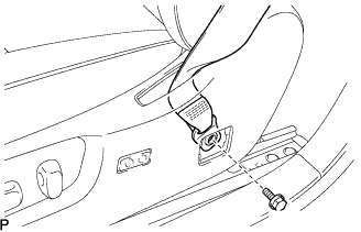 |
Move the seat using the power seat switch knob so that the seat belt anchor bolt is revealed.
Install the front seat outer belt anchor with the bolt.
Install the seat belt anchor cover cap.
Install the front seat belt hole cover.
| 46. CONNECT CABLE TO NEGATIVE BATTERY TERMINAL |
| 47. INSPECT PARKING BRAKE PEDAL TRAVEL |
Fully depress the parking brake pedal and release it to engage the parking brake.
Depress the pedal to the floor again, and release it to disengage the parking brake.
 |
Slowly depress the parking brake pedal to the floor, and count the number of clicks.
| 48. ADJUST PARKING BRAKE PEDAL TRAVEL |
Depress the parking brake pedal. Hold the wire adjusting No.1 nut using a wrench and loosen the lock nut.
Release the parking brake pedal.
 |
Turn the wire adjusting No.1 nut until the parking brake pedal travel meets the above specification.
Hold the wire adjusting No.1 nut using a wrench or equivalent tool and tighten the lock nut.
Count the number of clicks after depressing and releasing the parking brake pedal 3 or 4 times.
Check whether the parking brake drags or not.
When operating the parking brake pedal, check that the parking brake indicator light comes on.
| 49. PERFORM INITIALIZATION |
| 50. INSPECT SRS WARNING LIGHT |
| 51. INSPECT FRONT SEAT ASSEMBLY |
Check the power seat operation.
Check the seat heater operation (with seat heater).
Turn the engine switch on (IG).
Turn the seat heater switch ON.
Wait 5 minutes or more and confirm that the seat surface becomes warm.
| 52. CHECK FOR EXHAUST GAS LEAKS |
