FRONT AIRBAG SENSOR > INSTALLATION |
| 1. INSTALL FRONT AIRBAG SENSOR |
Check that the engine switch is off.
Check that the battery negative (-) terminal is disconnected.
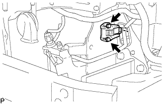 |
Connect the connector.
Install the front airbag sensor with the 2 bolts.
Check that there is no looseness in the installation parts of the front airbag sensor.
| 2. INSTALL HEADLIGHT ASSEMBLY |
 |
Attach the claw and install the headlight with the 3 screws.
w/ Headlight cleaner:
Connect the hose.
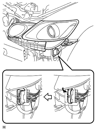 |
Connect the connector as shown in the illustration.
| 3. INSTALL FRONT BUMPER COVER |
Connect the ultrasonic sensor connector.
 |
Attach the 3 claws on the LH side.
Attach the 3 claws on the RH side.
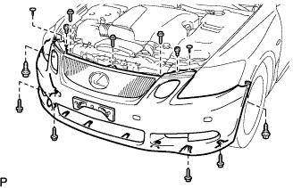 |
Install the bumper cover with the 2 clips, 6 screws and 5 bolts.
| 4. INSTALL COOL AIR INTAKE DUCT SEAL |
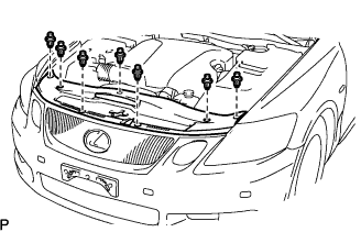 |
Install the duct seal with the 7 clips.
| 5. CONNECT CABLE TO NEGATIVE BATTERY TERMINAL |
| 6. PERFORM INITIALIZATION |
| 7. INSPECT SRS WARNING LIGHT |
| 8. VEHICLE PREPARATION FOR HEADLIGHT AIM ADJUSTMENT |
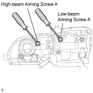 |
Adjust the aim vertically:
Adjust the headlight aim into the specified range by turning aiming screw A with a screwdriver.
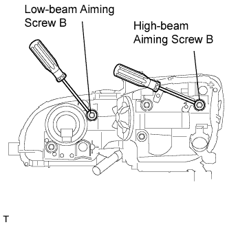 |
Adjust the aim horizontally:
Adjust the headlight aim into the specified range by turning aiming screw B with a screwdriver.
| 9. PREPARATION FOR HEADLIGHT AIMING |
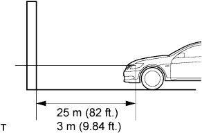 |
Prepare the vehicle according to the following conditions:
Prepare a piece of thick white paper (approximately 2 m (6.6 ft.) (height) x 4 m (13.1 ft.) (width)) to use as a screen.
Draw a vehicle center line down the center of the screen (V line).
Set the screen as shown in the illustration.
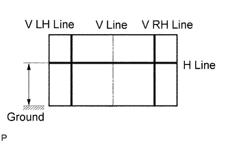 |
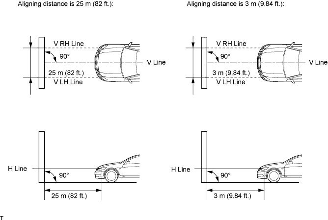
Draw base lines (H line, V LH, V RH lines) on the screen as shown in the illustration.
H Line (Headlight height):
Draw a horizontal line across the screen so that it passes through the center marks. the H line should be at the same height as the headlight bulb center marks of the low-beam headlights.
V LH Line, V RH Line (Center mark position of left-hand (LH) and right-hand (RH) headlights):
Draw two vertical lines so that they intersect the H line at each center mark (aligned with the center of the low-beam headlight bulbs).
| 10. HEADLIGHT AIMING INSPECTION |
Cover or disconnect the connector of the headlight on the opposite side to prevent light from the head-light not being inspected from affecting the headlight aiming inspection.
Start the engine.
w/ headlight leveling switch:
Set the headlight leveling switch to 0 (zero).
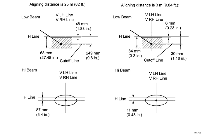
Turn on the headlight and make sure that the cutoff line falls within the specified area, as shown in the illustration.
| 11. HEADLIGHT AIMING ADJUSTMENT |
|
Adjust the aim vertically:
Adjust the headlight aim into the specified range by turning aiming screw A with a screwdriver.
|
Adjust the aim horizontally:
Adjust the headlight aim into the specified range by turning aiming screw B with a screwdriver.
| 12. ADJUST FOG LIGHT AIMING |
 |
The fog light aim can be adjusted by moving the aiming screw in the vertical direction.
