SLIDING ROOF SYSTEM > Sliding Roof ECU Power Source Circuit |

| 1.PERFORM ACTIVE TEST BY INTELLIGENT TESTER (SLIDING ROOF OPERATION) |
Select the Active Test, use the intelligent tester to generate a control command, and then check that the sliding roof operates normally.
| Item | Test Details | Diagnostic Note |
| Sliding Roof | Operate sliding roof SLIDE CLOSE / TILT UP CLOS/UP: Sliding roof SLIDE CLOSE or TILT UP operation occurs OFF: Sliding roof is not operating | - |
| Sliding Roof | Operate sliding roof SLIDE OPEN / TILT DOWN OPN/DWN: Sliding roof SLIDE OPEN or TILT DOWN operation occurs OFF: Sliding roof is not operating | - |
|
| ||||
| NG | |
| 2.INSPECT FUSE (S/ROOF, ECU-IG LH, AM2) |
Remove the S/ROOF and ECU-IG LH fuses from the cowl side junction block LH.
Remove the AM2 fuse from the cowl side junction block RH.
Measure the resistance of the fuses.
|
| ||||
| OK | |
| 3.INSPECT COWL SIDE JUNCTION BLOCK LH (LH-IG 2 RELAY) |
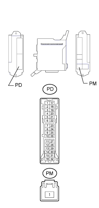 |
Disconnect the PD and PM junction block connectors.
Measure the resistance of the connectors.
| Tester Connection | Specified Condition |
| PD-29 - PM-1 | 10 kΩ or higher |
| PD-29 - PM-1 | Below 1 Ω (when battery voltage is applied to terminals PD-11 to PD-7 or PD-8) |
|
| ||||
| OK | |
| 4.CHECK WIRE HARNESS (SLIDING ROOF DRIVE GEAR - BATTERY AND BODY GROUND) |
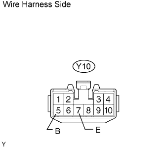 |
Disconnect the Y10 drive gear connector.
Measure the resistance and voltage of the wire harness side connector.
| Tester Connection | Specified Condition |
| Y10-7 (E) - Body ground | Below 1 Ω |
| Tester Connection | Specified Condition |
| Y10-5 (B) - Body ground | 10 to 14 V |
|
| ||||
| OK | |
| 5.CHECK WIRE HARNESS (SLIDING ROOF DRIVE GEAR - BODY GROUND) |
 |
Disconnect the Y10 drive gear connector.
Measure the voltage of the wire harness side connector.
| Tester Connection | Switch Condition | Specified Condition |
| Y10-6 (IG) - Body ground | Engine switch off | Below 1 V |
| Y10-6 (IG) - Body ground | Engine switch on (IG) | 10 to 14 V |
|
| ||||
| NG | |
| 6.CHECK WIRE HARNESS (PERSONAL LIGHT ASSEMBLY - BATTERY) |
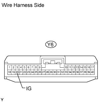 |
Disconnect the Y6 drive gear connector.
Measure the voltage of the wire harness side connector.
| Tester Connection | Switch Condition | Specified Condition |
| Y6-20 (IG) - Body ground | Engine switch off | Below 1 V |
| Y6-20 (IG) - Body ground | Engine switch on (IG) | 10 to 14 V |
|
| ||||
| OK | |
| 7.CHECK WIRE HARNESS (PERSONAL LIGHT ASSEMBLY - SLIDING ROOF DRIVE GEAR) |
 |
Disconnect the Y10 drive gear connector.
Disconnect the Y6 light connector.
Measure the resistance of the wire harness side connectors.
| Tester Connection | Specified Condition |
| Y6-5 (IG3) - Y10-6 (IG) | Below 1 Ω |
|
| ||||
| OK | ||
| ||
