SLIDING ROOF SYSTEM > Sliding Roof Control Switch Circuit |
| 1.PERFORM ACTIVE TEST BY INTELLIGENT TESTER (SLIDING ROOF OPERATION) |
Select the Active Test, use the intelligent tester to generate a control command, and then check that the sliding roof slides open / close and tilts up / down.
| Item | Test Details | Diagnostic Note |
| Sliding Roof | Operate sliding roof SLIDE CLOSE / TILT UP CLOS / UP: Sliding roof SLIDE CLOSE or TILT UP operation occurs OFF: Sliding roof is not operating | - |
| Sliding Roof | Operate sliding roof SLIDE OPEN / TILT DOWN OPEN / DOWN: Sliding roof SLIDE OPEN or TILT DOWN operation occurs OFF: Sliding roof is not operating | - |
|
| ||||
| OK | |
| 2.READ VALUE OF INTELLIGENT TESTER (SLIDING ROOF SWITCH) |
Use the Data List to check if the sliding roof switch is functioning properly.
| Item | Measurement Item / Range (Display) | Normal Condition | Diagnostic Note |
| Down Switch | Tilt switch down signal / ON or OFF | ON: TILT DOWN switch is pressed OFF: TILT DOWN switch is not pressed | - |
| Up Switch | Tilt switch up signal / ON or OFF | ON: TILT UP switch is pressed OFF: TILT UP switch is not pressed | - |
| Close Switch | Slide switch close signal / ON or OFF | ON: SLIDE CLOSE switch is pressed OFF: SLIDE CLOSE switch is not pressed | - |
| Open Switch | Slide switch open signal / ON or OFF | ON: SLIDE OPEN switch is pressed OFF: SLIDE OPEN switch is not pressed | - |
|
| ||||
| NG | |
| 3.INSPECT PERSONAL LIGHT ASSEMBLY (SLIDING ROOF SWITCH) |
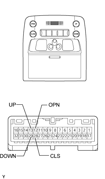 |
Remove the personal light.
Measure the resistance of the connector.
| Tester Connection | Switch Condition | Specified Condition |
| 13 (UP) - 8 (B) | TILT UP | Below 1 Ω |
| 13 (UP) - 8 (B) | Off | 10 kΩ or higher |
| 29 (DOWN) - 8 (B) | TILT DOWN | Below 1 Ω |
| 29 (DOWN) - 8 (B) | Off | 10 kΩ or higher |
| 12 (OPN) - 8 (B) | SLIDE OPEN | Below 1 Ω |
| 12 (OPN) - 8 (B) | Off | 10 kΩ or higher |
| 28 (CLS) - 8 (B) | SLIDE CLOSE | Below 1 Ω |
| 28 (CLS) - 8 (B) | Off | 10 kΩ or higher |
|
| ||||
| OK | |
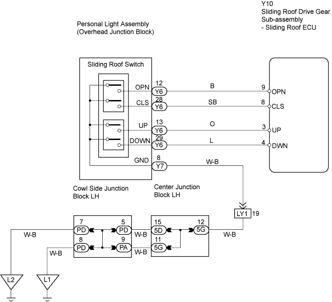
| 4.CHECK WIRE HARNESS (PERSONAL LIGHT ASSEMBLY - DRIVE GEAR AND BODY GROUND) |
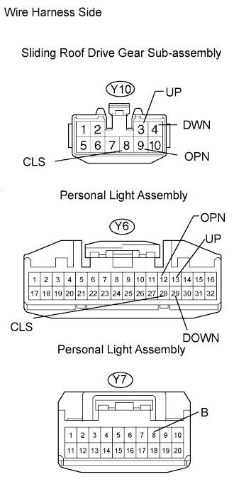 |
Disconnect the Y6 and Y7 light connectors.
Disconnect the Y10 drive gear connector.
Measure the resistance of the wire harness side connectors.
| Tester Connection | Specified Condition |
| Y6-13 (UP) - Y10-3 (UP) | Below 1 Ω |
| Y6-29 (DOWN) - Y10-4 (DWN) | Below 1 Ω |
| Y6-12 (OPN) - Y10-9 (OPN) | Below 1 Ω |
| Y6-28 (CLS) - Y10-8 (CLS) | Below 1 Ω |
| Y7-8 (B) - Body ground | Below 1 Ω |
|
| ||||
| OK | ||
| ||
