WATER PUMP > INSTALLATION |
| 1. CLEAN WATER PUMP ASSEMBLY |
| 2. INSTALL WATER PUMP ASSEMBLY |
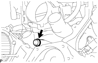 |
Install a new O-ring to the water by-pass hose.
 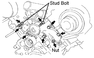 |
Install a new gasket and the water pump with the 5 bolts, 2 stud bolts and nut.
| 3. INSTALL NO. 2 TIMING BELT IDLER SUB-ASSEMBLY |
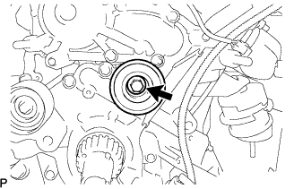 |
Install the pulley with the bolt.
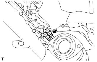
| 4. INSTALL WATER INLET HOUSING |
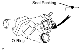 |
Install a new O-ring.
Apply soapy water to the O-ring.
Apply seal packing to the groove of the water inlet housing as shown in the illustration.
 |
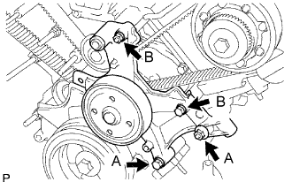
Install the water inlet housing with the 2 bolts. Then connect the water hose.
| Item | Specified Condition |
| Bolt A | 77 mm (3.03 in.) |
| Bolt B | 22 mm (0.86 in.) |
| 5. INSTALL TIMING BELT |
Check the No. 1 and No. 2 belt idlers.
Visually check the seal portion of the idler pulley for oil leakage.
Check that the idler turns smoothly.
 |
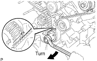
Check the water pump.
Visually check the air hole and water hole for coolant leakage.
Turn the pulley, and check that the water pump bearing moves smoothly and quietly.
Remove any oil or water on the crankshaft, oil pump pulley, water pump pulley, No. 1 and No. 2 idler. Keep them clean.
Set the No. 1 cylinder to TDC/compression.
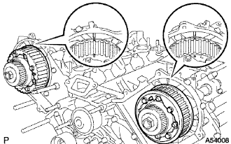 |
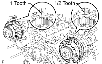
Turn the hexagon head portion of the camshaft to align the timing marks of the camshaft timing pulleys and timing belt plates.
 |
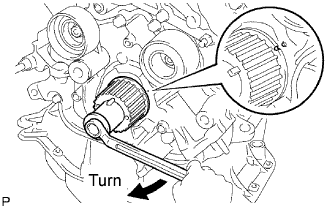 |
Using the crankshaft damper bolt, turn the crankshaft to align the timing marks of the crankshaft timing pulley and oil pump body.
 |
Remove any oil or water on each pulley. Keep them clean.
Face the front mark (arrow) on the belt forward.
Connect the belt to the crankshaft timing pulley. Align the installation mark on the belt with the timing mark of the crankshaft timing pulley.
Connect the belt to the No. 2 idler.
Connect the belt to the camshaft timing pulley (LH bank). Align the installation mark on the belt with the timing mark of the camshaft timing pulley.
Connect the belt to the water pump pulley.
Connect the belt to the camshaft timing pulley (RH bank). Align the installation mark on the belt with the timing mark of the camshaft timing pulley.
Connect the timing belt to the No. 1 idler.
 |
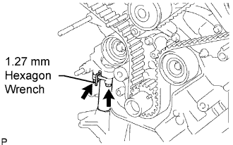
Set the belt tensioner.
Using a press, slowly press in the push rod using 981 to 9,807 N (100 to 1,000 kgf, 220 to 2,205 lbf) of pressure.
Align the holes of the push rod and housing. Pass a 1.27 mm hexagon wrench through the holes to keep the setting position of the push rod.
Release the press.
Install the dust boot to the belt tensioner.
 |
Install the belt tensioner.
Temporarily install the belt tensioner with the 2 bolts.
Alternately tighten the 2 bolts.
Using pliers, remove the 1.27 mm hexagon wrench from the belt tensioner.
 |
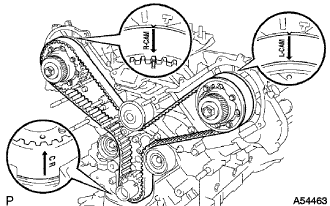
Check the valve timing.
Using the crankshaft damper bolt, slowly turn the crankshaft timing pulley 2 revolutions from TDC to TDC.
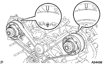 |
Check that each pulley aligns with the timing marks as shown in the illustration.
Remove the crankshaft damper bolt.
| 6. INSTALL NO. 1 CRANKSHAFT POSITION SENSOR PLATE |
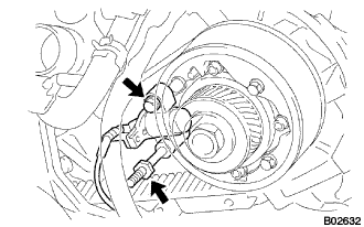 |
Install the sensor with the bolt and stud bolt.
| 7. INSTALL TIMING GEAR COVER SPACER |
Install a new gasket and cover spacer.
| 8. INSTALL NO. 1 TIMING BELT COVER |
Install the timing belt cover with the 4 bolts.
| 9. INSTALL NO. 2 TIMING BELT COVER SUB-ASSEMBLY |
 |
Set the No. 2 cover by matching the claws and pin with each part.
Install the timing belt cover with the 2 bolts.
| 10. INSTALL IDLER PULLEY ASSEMBLY |
 |
Install the idler with the 2 bolts and 2 nuts.
| 11. INSTALL NO. 3 TIMING BELT COVER SUB-ASSEMBLY RH |
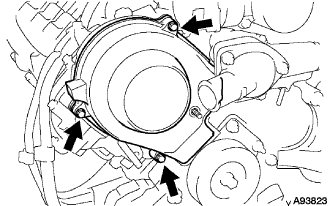 |
Install the gasket to the cover.
Install the cover with the cap nut and 3 bolts.
| 12. INSTALL NO. 3 TIMING BELT COVER SUB-ASSEMBLY LH |
 |
Install the gasket to the cover.
Pass the camshaft position sensor wire through the cover hole.
Install the cover with the 4 bolts.
Install the wire grommet to the cover.
Install the sensor connector to the sensor holder.
Connect the sensor connector.
Install the sensor wire to the wire clamp on the cover.
Install the engine wire to the 2 wire clamps on the cover.
| 13. CONNECT OIL COOLER PIPE |
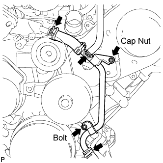 |
Connect the 3 water by-pass hoses as shown in the illustration.
Install the oil cooler pipe to the cover with the cap nut and the bolt.
| 14. INSTALL CRANKSHAFT DAMPER SUB-ASSEMBLY |
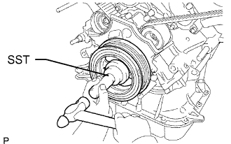 |
Align the damper set key with the key groove of the crankshaft damper.
Using SST and a hammer, tap in the crankshaft damper.
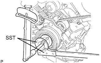 |
Using SST, install the damper bolt.
| 15. INSTALL NO. 2 IDLER PULLEY SUB-ASSEMBLY |
Install the pulley with the bolt.
| 16. INSTALL V-RIBBED BELT TENSIONER ASSEMBLY |
 |
Install the belt tensioner with the bolt and 2 nuts.
| 17. INSTALL COMPRESSOR ASSEMBLY |
 |
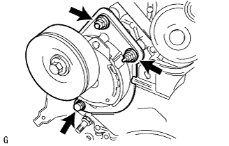
Hang the compressor bracket onto the fan bracket and temporarily install the compressor with the bolt.
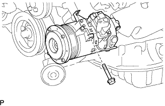
 |
Install the compressor with the 3 bolts, nut and bracket.
| 18. INSTALL GENERATOR ASSEMBLY |
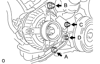 |
Install the generator with the bolt and 2 nuts.
Install the ground cable with the bolt D.
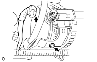 |
Install the battery cable with the nut, and then attach the rubber cap.
Install the bracket with the bolt.
Connect the cable to the generator.
| 19. INSTALL V-RIBBED BELT |
 |
Set the V-belt to everything except the No. 2 idler pulley, as shown in the illustration.
Loosen the V-belt by turning the belt tensioner counterclockwise.
Then set the V-belt to the idler pulley.
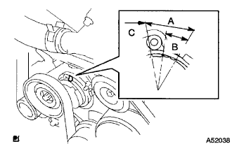 |
After a new belt has been installed, check that the mark is within the A range shown in the illustration.
| 20. INSTALL RADIATOR ASSEMBLY |
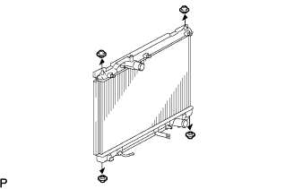 |
Install the 2 radiator support cushions and 2 radiator lower supports to the radiator.
 |
Install the fan to the radiator, and attach the 3 claws.
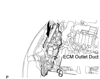 |
Install the radiator and attach the ECM outlet duct.
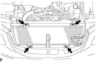 |
Align the radiator with the condenser. Then install the radiator with the 4 bolts.
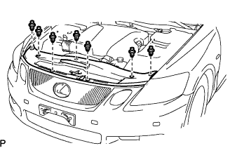
| 21. INSTALL UPPER RADIATOR SUPPORT SUB-ASSEMBLY |
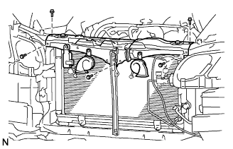 |
Install the radiator support with the 5 bolts.
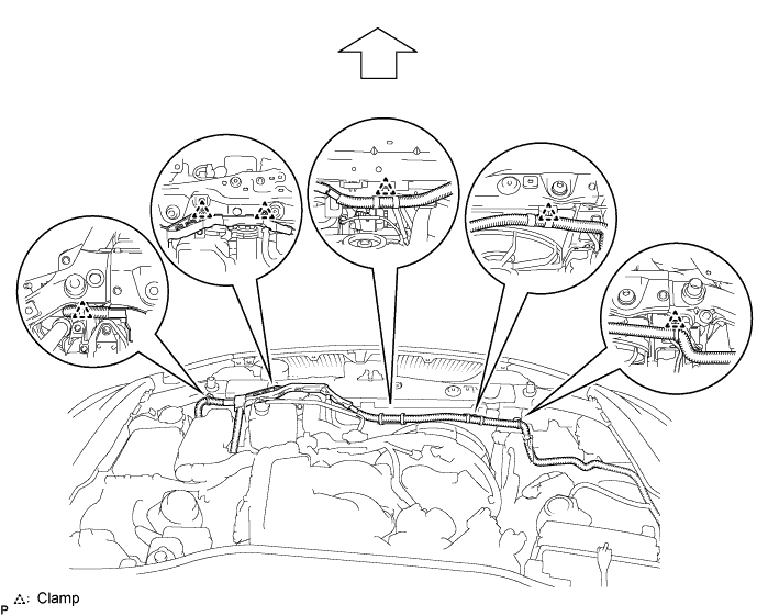
Attach the 6 clamps and install the wire harness.
| 22. INSTALL HOOD LOCK ASSEMBLY |
 |
Apply MP grease to the sliding areas of the lock.
 |
Install the hood lock.
Install the 2 bolts and nut.
Install a new cap.
Connect the hood lock control cable.
| 23. INSTALL HOOD LOCK CONTROL CABLE COVER |
 |
Attach the claw and install the cable cover.
Install the 3 screws.
| 24. INSTALL RADIATOR SUPPORT OPENING COVER |
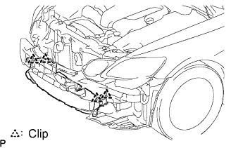 |
Install the cover with the 4 clips.
| 25. INSTALL FRONT BUMPER COVER |
Connect the ultrasonic sensor connector.
 |
Attach the 3 claws on the LH side.
Attach the 3 claws on the RH side.
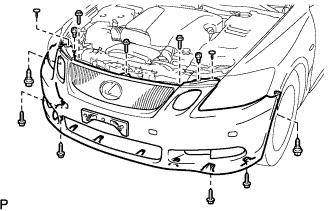 |
Install the bumper cover with the 2 clips, 6 screws and 5 bolts.
| 26. DISCONNECT NO. 1 OIL COOLER OUTLET TUBE |
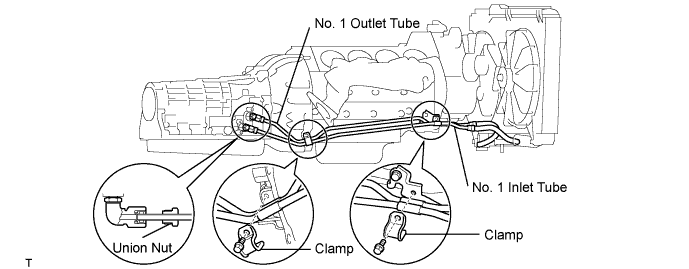
Temporarily install the oil cooler outlet tube.
Temporarily install the oil cooler inlet tube.
Install the 2 clamps with the 2 bolts.
 |
Tighten the oil cooler outlet tube No. 1.
| 27. DISCONNECT NO. 1 OIL COOLER INLET TUBE |
 |
Tighten the oil cooler inlet tube.
| 28. CONNECT RADIATOR HOSE OUTLET |
 |
Connect the hose outlet.
| 29. CONNECT RADIATOR HOSE INLET |
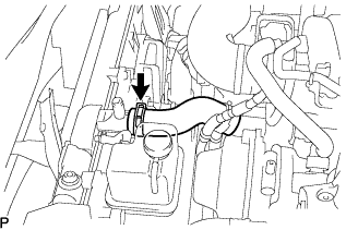 |
Connect the hose inlet.
| 30. ADD ENGINE COOLANT |
Tighten the radiator drain cock plug by hand.
Tighten the 2 cylinder block drain cock plugs.
Add engine coolant.
Install the vent plug.
Slowly pour coolant into the radiator reservoir until it reaches the FULL line.
Press the inlet and outlet radiator hoses several times by hand, and then check the level of the coolant.
If the coolant level is low, add coolant.
Install the radiator cap.
Bleed air from the cooling system.
Warm up the engine until the thermostat opens. While the thermostat is open, circulate the coolant for several minutes.
Maintain the engine speed at 2,000 to 2,500 rpm.
Press the inlet and outlet radiator hoses several times by hand to bleed air.
Stop the engine, and wait until the engine coolant cools down to ambient temperature.
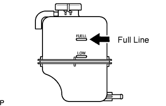 |
Check the coolant level in the radiator reservoir.
If the coolant level is low, add SLLC to the radiator reservoir FULL line.
| 31. CHECK FOR ENGINE COOLANT LEAKS |
Check for engine coolant leaks (Click here).
| 32. INSTALL AIR CLEANER ASSEMBLY |
Install the air cleaner assembly with the 3 bolts.
 |
Connect the MAF meter connector and clamp to the air cleaner.
| 33. INSTALL NO. 1 AIR CLEANER INLET |
Install the inlet with the bolt.
| 34. INSTALL ENGINE ROOM SIDE COVER LH |
 |
Install the side cover with the 3 clips.
| 35. INSTALL ENGINE ROOM SIDE COVER RH |
 |
Install the side cover with the 2 clips and nut.
| 36. INSTALL COOL AIR INTAKE DUCT SEAL |
 |
Install the duct seal with the 7 clips.
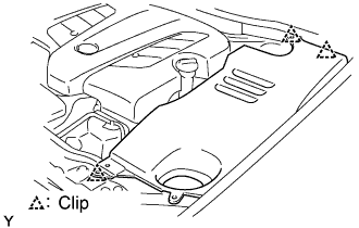
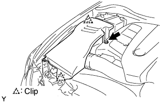
| 37. INSTALL V-BANK COVER SUB-ASSEMBLY |
Install the cover with the 2 nuts.
| 38. INSTALL ENGINE UNDER COVER |
Connect the ultrasonic sensor connector.
|
Attach the 3 claws on the LH side.
Attach the 3 claws on the RH side.
|
Install the bumper cover with the 2 clips, 6 screws and 5 bolts.
| 39. CONNECT CABLE TO NEGATIVE BATTERY TERMINAL |
| 40. PERFORM INITIALIZATION |
Perform initialization (Click here).
