GENERATOR > INSTALLATION |
| 1. INSTALL GENERATOR ASSEMBLY |
 |
Install the generator with the 2 bolts.
 |
Install the bracket with the bolt and nut.
 |
Install the battery cable with the nut.
Install the bracket of the wire harness to the generator with the bolt.
Attach the clamp of the wire harness to the generator.
Connect the cable to the generator, and then attach the rubber cap.
| 2. INSTALL NO. 2 IDLER PULLEY SUB-ASSEMBLY |
Install the idler pulley and pulley plate with the bolt.
| 3. INSTALL COMPRESSOR ASSEMBLY |
 |
Using an E8 "torx" socket, install the compressor with the stud bolt.
 |
Install the compressor with the 3 bolts and nut.
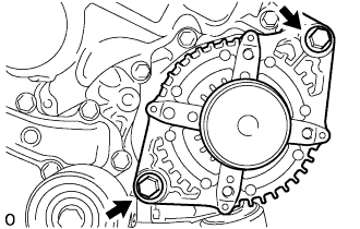
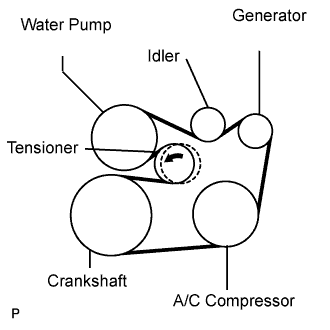
| 4. INSTALL V-RIBBED BELT |
 |
Install the V-ribbed belt.
While turning the belt tensioner counterclockwise, remove the bar.
 |
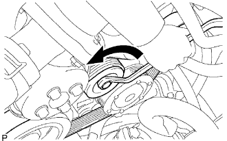
If it is difficult to install the V-ribbed belt, perform the following procedure.
Put the V-ribbed belt on everything except the tensioner pulley as shown in the illustration.
While releasing the belt tension by turning the belt tensioner counterclockwise, put the V-ribbed belt on the tensioner pulley.
| 5. INSTALL ENGINE UNDER COVER |
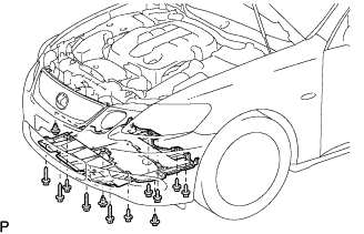 |
Install the under cover with the 3 clips and 10 screws.
| 6. INSTALL ENGINE ROOM SIDE COVER LH |
 |
Install the side cover with the 3 clips.
| 7. INSTALL COOL AIR INTAKE DUCT SEAL |
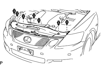 |
Install the duct seal with the 7 clips.
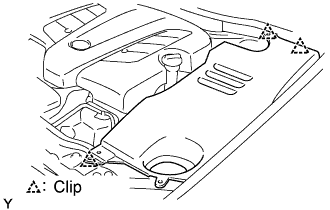
| 8. INSTALL V-BANK COVER SUB-ASSEMBLY |
Install the cover with the 2 nuts.
| 9. CONNECT CABLE TO NEGATIVE BATTERY TERMINAL |
| 10. PERFORM INITIALIZATION |
Perform initialization (Click here).
