CRUISE CONTROL SYSTEM > TC and CG Terminal Circuit |
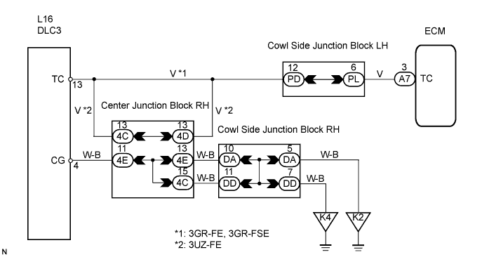
| 1.CHECK WIRE HARNESS (TC OF DLC3 - ECM) |
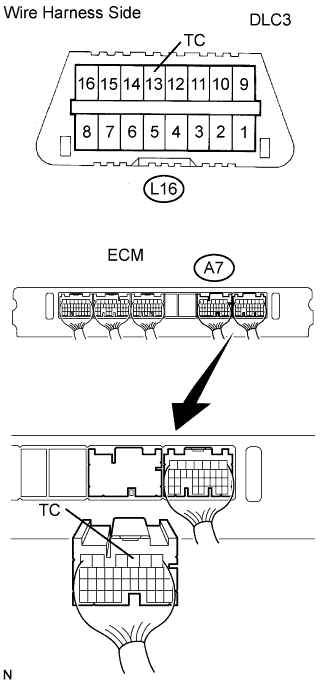 |
Disconnect the A7 ECM connector.
Measure the resistance of the wire harness side connectors.
| Tester Connection | Condition | Specified Condition |
| A7-3 (TC) - L16-13 (TC) | Always | Below 1 Ω |
|
| ||||
| OK | |
| 2.CHECK WIRE HARNESS (CG OF DLC3 - BODY GROUND) |
 |
Measure the resistance of the connector.
| Tester Connection | Condition | Specified Condition |
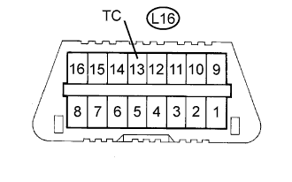
| L16-4 (CG) - Body ground | Always | Below 1 Ω |
|
| ||||
| OK | |
| 3.CHECK WIRE HARNESS (TC OF DLC3 - BODY GROUND) |
 |
Measure the resistance of the connector.
| Tester Connection | Condition | Specified Condition |
| L16-13 (TC) - Body ground | Always | 10 kΩ or higher |
|
| ||||
| OK | ||
| ||
