METER / GAUGE SYSTEM > Entire Combination Meter does not Operate |

| 1.INSPECT COMBINATION METER (POWER SOURCE SYSTEM) |
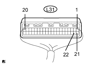 |
Disconnect the L31 connector.
Measure the resistance of the wire harness side connector.
| Terminal No. | Condition | Specified Condition |
| L31-20 - Body ground | Always | Below 1 Ω |
Measure the voltage of the wire harness side connector.
| Terminal No. | Condition | Specified Condition |
| L31-1 - Body ground | Always | 10 to 14 V |
| L31-21 - Body ground | Always | 10 to 14 V |
| L31-22 - Body ground | Always | 10 to 14 V |
|
| ||||
| OK | |
| 2.INSPECT COMBINATION METER (AUTOMATIC LIGHT CONTROL SENSOR SYSTEM) |
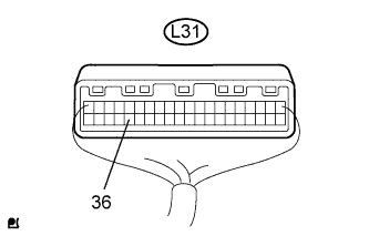 |
Disconnect the L31 connector.
Measure the resistance of the wire harness side connector.
| Terminal No. | Condition | Specified Condition |
| L31-36 - Body ground | Always | 10 kΩ or higher |
|
| ||||
| OK | ||
| ||
| 3.INSPECT AUTOMATIC LIGHT CONTROL SENSOR |
Disconnect the W33 automatic light control sensor connector.
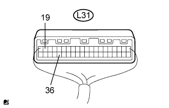 |
Disconnect the L31 connector.
Measure the resistance of the wire harness side connector.
| Terminal No. | Condition | Specified Condition |
| L31-36 - L31-18 | Always | 10 kΩ or higher |
| L31-36 - Body ground | Always | 10 kΩ or higher |
|
| ||||
| OK | ||
| ||
