METER / GAUGE SYSTEM > Malfunction in Speedometer |

| 1.PERFORM ACTIVE TEST BY INTELLIGENT TESTER |
Operate the intelligent tester according to the display and select the "Active Test".
| Item | Test Details | Diagnostic Note |
| Speed Meter Operation | 0 / 40 (24) / 80 (48) / 120 (72) / 160 (96) / 200 (120) / 240 (149) km/h (mph) | - |
|
| ||||
| OK | |
| 2.READ VALUE OF INTELLIGENT TESTER |
Operate the intelligent tester according to the display and select the "Data List".
| Item | Measurement Item / Range (Display) | Normal Condition | Diagnostic Note |
| Vehicle Speed Meter | Vehicle speed / Min.: 0 km/h (0 mph), Max.: 255 km/h (158 mph) | Almost same as actual vehicle speed (When driving) | - |
|
| ||||
| OK | ||
| ||
| 3.READ VALUE OF INTELLIGENT TESTER |
Operate the intelligent tester according to the display and select the "Data List".
| Item | Measurement Item / Range (Display) | Normal Condition | Diagnostic Note |
| FR WHEEL SPD | Wheel speed sensor (FR) reading/ Min.: 0 km/h (0 mph), Max.: 326 km/h (202 mph) | Almost same as actual vehicle speed (When driving) | - |
| FL WHEEL SPD | Wheel speed sensor (FL) reading/ Min.: 0 km/h (0 mph), Max.: 326 km/h (202 mph) | Almost same as actual vehicle speed (When driving) | - |
| RR WHEEL SPD | Wheel speed sensor (RR) reading/ Min.: 0 km/h (0 mph), Max.: 326 km/h (202 mph) | Almost same as actual vehicle speed (When driving) | - |
| RL WHEEL SPD | Wheel speed sensor (RL) reading/ Min.: 0 km/h (0 mph), Max.: 326 km/h (202 mph) | Almost same as actual vehicle speed (When driving) | - |
|
| ||||
| OK | |
| 4.INSPECT COMBINATION METER |
 |
Check the input signal waveform.
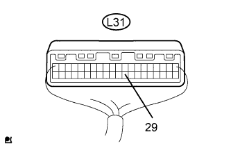
Remove the combination meter with the connector still connected.
Connect the oscilloscope to the terminals L31-29 and body ground.
Start the engine.
 |
Check the signal waveform of the connector.
| Item | Condition |
| Tool Setting | 5 V/DIV, 20 msec/DIV. |
| Vehicle Condition | Driving at approx. 20 km/h (12 mph) |
|
| ||||
| OK | ||
| ||
| 5.CHECK HARNESS AND CONNECTOR (COMBINATION METER - SKID CONTROL ECU) |
 |
3UZ-FE:
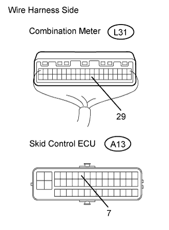
Disconnect the L31 meter connector.
Disconnect the A13 meter connector.
Measure the resistance of the wire harness side connectors.
| Tester Connection | Condition | Specified Condition |
| L31-29 - A13-7 | Always | Below 1 Ω |
| L31-29 - Body ground | Always | 10 kΩ or higher |
 |
3GR-FE, 3GR-FSE:
Disconnect the L31 meter connector.
Disconnect the A48 meter connector.
Measure the resistance of the wire harness side connectors.
| Tester Connection | Condition | Specified Condition |
| L31-29 - A48-12 | Always | Below 1 Ω |
| L31-29 - Body ground | Always | 10 kΩ or higher |
|
| ||||
| OK | |
| 6.INSPECT SKID CONTROL ECU |
3UZ-FE:
 |
Disconnect the A13 ECU connector.
Measure the voltage of the wire harness side connector.
| Tester Connection | Condition | Specified Condition |
| A13-7 - Body ground | Engine switch on (IG) | 10 to 14 V |
3GR-FE, 3GR-FSE:
 |
Disconnect the A48 ECU connector.
Measure the voltage of the wire harness side connector.
| Tester Connection | Condition | Specified Condition |
| A48-12 - Body ground | Engine switch on (IG) | 10 to 14 V |
|
| ||||
| OK | ||
| ||
