METER / GAUGE SYSTEM > Malfunction in Tachometer |
| 1.PERFORM ACTIVE TEST BY INTELLIGENT TESTER |
Operate the intelligent tester according to the display and select the "Active Test".
| Item | Test Details | Diagnostic Note |
| TachoMeter Operation | 0 rpm / 1,000 rpm / 2,000 rpm / 3,000 rpm / 4,000 rpm / 5,000 rpm / 6,000 rpm / 7,000 rpm | - |
|
| ||||
| OK | |
| 2.READ VALUE OF INTELLIGENT TESTER (ENGINE SPEED SIGNAL) |
Operate the intelligent tester according to the display and select the "Data List".
| Item | Measurement Item/Range (Display) | Normal Condition | Diagnostic Note |
| Engine Rpm | Engine speed/ Min.: 0 rpm, Max.: 12,750 rpm | Almost same as actual engine speed (when engine is running) | - |
|
| ||||
| OK | ||
| ||
| 3.READ VALUE OF INTELLIGENT TESTER (ENGINE SPEED SIGNAL) |
Operate the intelligent tester according to the steps on the display and select the "Data List".
| Item | Measurement Item/Range (Display) | Normal Condition | Diagnostic Note |
| Engine Speed | Engine speed/ Min.: 0 rpm, Max.: 16,383 rpm | Almost same as actual engine speed (When engine is running) | - |
|
| ||||
| OK | |
| 4.INSPECT COMBINATION METER |
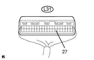 |
Check the input signal waveform.
Remove the combination meter with the connector still connected.
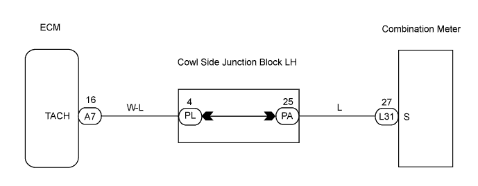
Connect the oscilloscope to terminal L31-27 and body ground.
Start the engine.
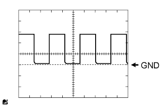 |
Check the signal waveform of the connector.
| Item | Condition |
| Tool Setting | 5 V/DIV., 10 msec./DIV. |
| Vehicle Condition | Engine idle speed |
|
| ||||
| OK | |
| 5.CHECK HARNESS AND CONNECTOR (COMBINATION METER - ECM) |
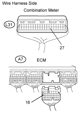 |
Disconnect the A7 ECM connector.
Disconnect the L31 meter connector.
Measure the resistance of the wire harness side connectors.
| Tester Connection | Condition | Specified Condition |
| L31-27 - A7-16 | Always | Below 1 Ω |
| L31-27 - Body ground | Always | 10 kΩ or higher |
|
| ||||
| OK | ||
| ||
