METER / GAUGE SYSTEM > Malfunction in Fuel Receiver Gauge |
| 1.PERFORM ACTIVE TEST BY INTELLIGENT TESTER |
Operate the intelligent tester according to the display and select the "Active Test".
| Item | Test Details | Diagnostic Note |
| Fuel Meter Operation | EMPTY, 1/2, FULL | - |
|
| ||||
| OK | |
| 2.READ VALUE OF INTELLIGENT TESTER |
Operate the intelligent tester according to the display and select the "Data List".
| Item | Measurement Item/Range (Display) | Normal Condition | Diagnostic Note |
| Fuel Input | Fuel input signal/ Min.: 0, Max.: 255 | Fuel gauge indicates (F): 47 Fuel gauge indicates (3/4): 92 Fuel gauge indicates (1/2): 148 Fuel gauge indicates (1/4): 187 Fuel gauge indicates (E): 205 | - |
|
| ||||
| OK | |
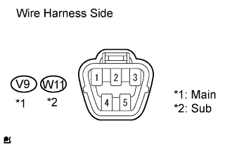
| 3.INSPECT FUEL SENDER GAUGE ASSEMBLY (MAIN) |
 |
Measure the voltage of the wire harness side connector.
| Tester Connection | Condition | Specified Condition |
| V9-2 - V9-3 | Engine switch on (ACC) or on (IG) | 10 to 14 V |
Remove the fuel sender gauge assembly.
Connect the fuel sender gauge connector.
 |
Check that the float position is between E and F.
Measure the resistance between the terminals 2 and 1 of connector of the connector.
| Float level | Float Position | Specified Condition |
| F | 51.4 to 57.4 mm (2.02 to 2.26 in.) | 6.5 to 8.5 Ω |
| E | 121.7 to 127.7 mm (4.79 to 5.03 in.) | 237.6 to 242.6 Ω |
|
| ||||
| OK | |
| 4.INSPECT FUEL SENDER GAUGE ASSEMBLY (SUB) |
 |
Measure the voltage of the wire harness side connector.
| Tester Connection | Condition | Specified Condition |
| W11-2 - W11-3 | Engine switch on (ACC) or on (IG) | 10 to 14 V |
Remove the fuel sender gauge assembly.
Connect the fuel sender gauge connector.
 |
Check that the float position is between E and F.
Measure the resistance between terminals 2 and 1 of connector of the connector.
| Float level | Float Position | Specified Condition |
| F | 69.9 to 75.9 mm (2.75 to 2.99 in.) | 6.5 to 8.5 Ω |
| E | 103.1 to 109.1 mm (4.06 to 4.30 in.) | 167.9 to 171.9 Ω |
|
| ||||
| OK | |
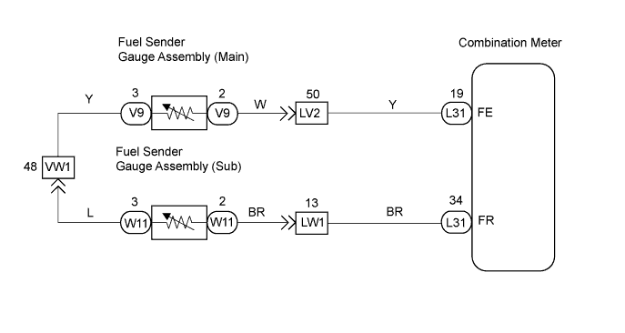
| 5.CHECK HARNESS AND CONNECTOR (COMBINATION METER - FUEL SENDER GAUGE (MAIN)) |
 |
Disconnect the V9 fuel sender gauge connector.
Disconnect the L31 meter connector.
Measure the resistance of the wire harness side connector.
| Tester Connection | Condition | Specified Condition |
| L31-19 - V9-2 | Always | Below 1 Ω |
| V9-2 - Body ground | Always | 10 kΩ or higher |
|
| ||||
| OK | |
| 6.CHECK HARNESS AND CONNECTOR (FUEL SENDER GAUGE (SUB) - FUEL SENDER GAUGE (MAIN)) |
 |
Disconnect the V9 fuel sender gauge connector.
Disconnect the W11 fuel sender gauge connector.
Measure the resistance of the wire harness side connectors.
| Tester Connection | Condition | Specified Condition |
| V9-3 - W11-3 | Always | Below 1 Ω |
| W11-3 - Body ground | Always | 10 kΩ or higher |
|
| ||||
| OK | |
| 7.CHECK HARNESS AND CONNECTOR (COMBINATION METER - FUEL SENDER GAUGE (SUB)) |
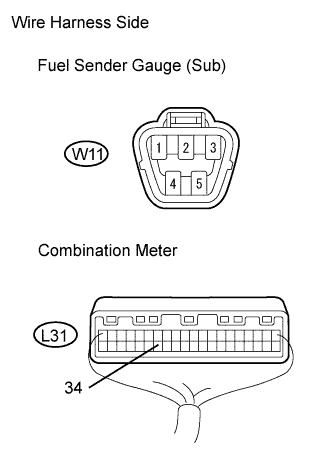 |
Disconnect the W11 fuel sender gauge connector.
Disconnect the L31 meter connector.
Measure the resistance of the wire harness side connectors.
| Tester Connection | Condition | Specified Condition |
| W11-2 - L31-34 | Always | Below 1 Ω |
| L31-34 - Body ground | Always | 10 kΩ or higher |
|
| ||||
| OK | ||
| ||
