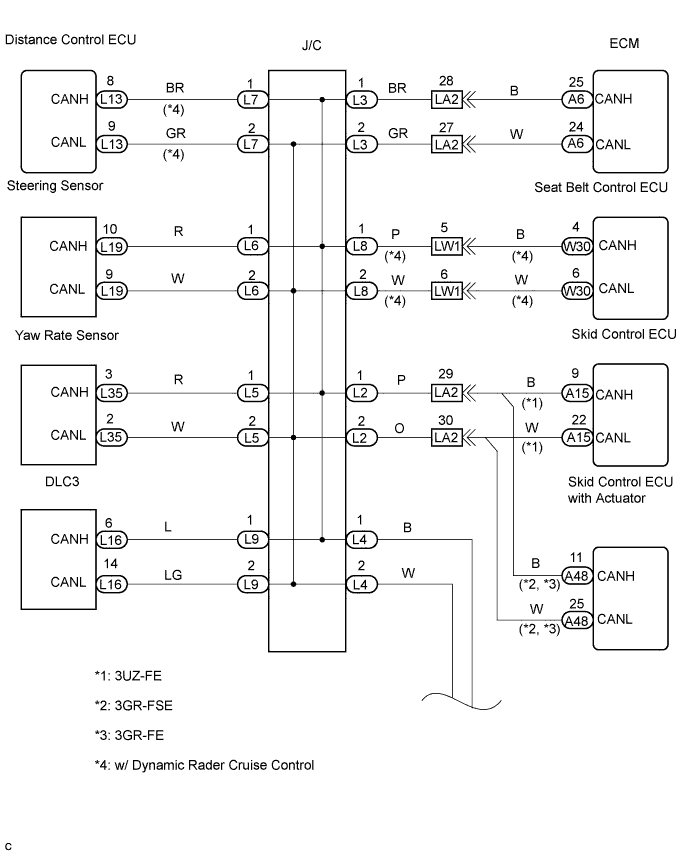
CAN COMMUNICATION SYSTEM > Check CAN Bus Lines for Short Circuit (LHD Models) |
| Symptom | Trouble Area |
| Resistance between terminals 6 (CANH) and 14 (CANL) of the DLC3 is below 54 Ω. |
|

| 1.CHECK CAN BUS LINES FOR SHORT CIRCUIT (DLC3 SUB BUS LINE) |
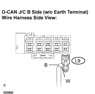 |
Disconnect the DLC3 sub bus line connector (L9) from the D-CAN J/C B side (w/o earth terminal).
 |
Measure the resistance according to the value(s) in the table below.
| Tester connection | Condition | Specified value |
| L16-6 (CANH) - L16-14 (CANL) | Engine Switch off | 1 MΩ or more |
|
| ||||
| OK | |
| 2.CONNECT CONNECTOR |
Reconnect the DLC3 sub bus line connector (L9) to the D-CAN J/C B side (w/o earth terminal).
| NEXT | |
| 3.CHECK CAN BUS LINES FOR SHORT CIRCUIT (CAN BUSES TO P-CAN J/C) |
 |
Disconnect the CAN main bus line connector (L78) from the P-CAN J/C B side (w/o earth terminal).
|
Measure the resistance according to the value(s) in the table below.
| Tester connection | Condition | Specified value |
| L16-6 (CANH) - L16-14 (CANL) | Engine Switch off | 108 to 132 Ω |
|
| ||||
| NG | |
| 4.CONNECT CONNECTOR |
Reconnect the CAN main bus line connector (L78) to the P-CAN J/C B side (w/o earth terminal).
| NEXT | |
| 5.CHECK CAN BUS LINES FOR SHORT CIRCUIT (DISTANCE CONTROL ECU) |
 |
Disconnect the distance control ECU sub bus line connector (L7) from the D-CAN J/C B side (w/o earth terminal).
|
Measure the resistance according to the value(s) in the table below.
| Tester connection | Condition | Specified value |
| L16-6 (CANH) - L16-14 (CANL) | Engine Switch off | 54 to 69 Ω |
|
| ||||
| NG | |
| 6.CONNECT CONNECTOR |
Reconnect the distance control ECU sub bus line connector (L7) to the D-CAN J/C B side (w/o earth terminal).
| NEXT | |
| 7.CHECK CAN BUS LINES FOR SHORT CIRCUIT (STEERING SENSOR) |
 |
Disconnect the steering sensor sub bus line connector (L6) from the D-CAN J/C B side (w/o earth terminal).
|
Measure the resistance according to the value(s) in the table below.
| Tester connection | Condition | Specified value |
| L16-6 (CANH) - L16-14 (CANL) | Engine Switch off | 54 to 69 Ω |
|
| ||||
| NG | |
| 8.CONNECT CONNECTOR |
Reconnect the steering sensor sub bus line connector (L6) to the D-CAN J/C B side (w/o earth terminal).
| NEXT | |
| 9.CHECK CAN BUS LINES FOR SHORT CIRCUIT (SEAT BELT CONTROL ECU) |
 |
Disconnect the seat belt control ECU sub bus line connector (L8) from the D-CAN J/C B side (w/o earth terminal).
|
Measure the resistance according to the value(s) in the table below.
| Tester connection | Condition | Specified value |
| L16-6 (CANH) - L16-14 (CANL) | Engine Switch off | 54 to 69 Ω |
|
| ||||
| NG | |
| 10.CONNECT CONNECTOR |
Reconnect the seat belt control ECU sub bus line connector (L8) to the D-CAN J/C B side (w/o earth terminal).
| NEXT | |
| 11.CHECK CAN BUS LINES FOR SHORT CIRCUIT (SKID CONTROL ECU WITH ACTUATOR) |
 |
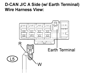
Disconnect the skid control ECU with actuator sub bus line connector (L2) from the D-CAN J/C A side (w/ earth terminal).
|
Measure the resistance according to the value(s) in the table below.
| Tester connection | Condition | Specified value |
| L16-6 (CANH) - L16-14 (CANL) | Engine Switch off | 54 to 69 Ω |
|
| ||||
| NG | |
| 12.CONNECT CONNECTOR |
Reconnect the skid control ECU with actuator sub bus line connector (L2) to the D-CAN J/C A side (w/ earth terminal).
| NEXT | |
| 13.CHECK CAN BUS LINES FOR SHORT CIRCUIT (SKID CONTROL ECU) |
|
Disconnect the skid control ECU sub bus line connector (L2) from the D-CAN J/C A side (w/ earth terminal).
|
Measure the resistance according to the value(s) in the table below.
| Tester connection | Condition | Specified value |
| L16-6 (CANH) - L16-14 (CANL) | Engine Switch off | 54 to 69 Ω |
|
| ||||
| NG | |
| 14.CONNECT CONNECTOR |
Reconnect the skid control ECU sub bus line connector (L2) to the D-CAN J/C A side (w/ earth terminal).
| NEXT | |
| 15.CHECK CAN BUS LINES FOR SHORT CIRCUIT (ECM) |
 |
Disconnect the ECM sub bus line connector (L3) from the D-CAN J/C A side (w/ earth terminal).
|
Measure the resistance according to the value(s) in the table below.
| Tester connection | Condition | Specified value |
| L16-6 (CANH) - L16-14 (CANL) | Engine Switch off | 54 to 69 Ω |
|
| ||||
| NG | |
| 16.CONNECT CONNECTOR |
Reconnect the ECM sub bus line connector (L3) to the D-CAN J/C A side (w/ earth terminal).
| NEXT | |
| 17.CHECK CAN BUS LINES FOR SHORT CIRCUIT (YAW RATE SENSOR) |
 |
Disconnect the yaw rate sensor sub bus line connector (L5) from the D-CAN J/C A side (w/ earth terminal).
|
Measure the resistance according to the value(s) in the table below.
| Tester connection | Condition | Specified value |
| L16-6 (CANH) - L16-14 (CANL) | Engine Switch off | 54 to 69 Ω |
|
| ||||
| NG | |
| 18.CONNECT CONNECTOR |
Reconnect the yaw rate sensor sub bus line connector (L5) to the D-CAN J/C A side (w/ earth terminal).
| NEXT | |
| 19.CHECK CAN BUS LINES FOR SHORT (CAN MAIN BUS LINE) |
 |
Disconnect the CAN main bus line connector (L4) from the D-CAN J/C A side (w/ earth terminal).
|
Measure the resistance according to the value(s) in the table below.
| Tester connection | Condition | Specified value |
| L16-6 (CANH) - L16-14 (CANL) | Engine Switch off | 54 to 69 Ω |
|
| ||||
| NG | ||
| ||
| 20.CONNECT CONNECTOR |
Reconnect the distance control ECU sub bus line connector (L7) to the D-CAN J/C B side (w/o earth terminal).
| NEXT | |
| 21.CHECK CAN BUS LINES FOR SHORT CIRCUIT (DISTANCE CONTROL ECU SUB BUS LINE) |
Disconnect the distance control ECU connector (L13).
|
Measure the resistance according to the value(s) in the table below.
| Tester connection | Condition | Specified value |
| L16-6 (CANH) - L16-14 (CANL) | Engine Switch off | 54 to 69 Ω |
|
| ||||
| NG | ||
| ||
| 22.CONNECT CONNECTOR |
Reconnect the steering sensor sub bus line connector (L6) to the D-CAN J/C B side (w/o earth terminal).
| NEXT | |
| 23.CHECK CAN BUS LINES FOR SHORT CIRCUIT (STEERING SENSOR SUB BUS LINE) |
Disconnect the steering sensor connector (L19).
|
Measure the resistance according to the value(s) in the table below.
| Tester connection | Condition | Specified value |
| L16-6 (CANH) - L16-14 (CANL) | Engine Switch off | 54 to 69 Ω |
|
| ||||
| NG | ||
| ||
| 24.CONNECT CONNECTOR |
Reconnect the seat belt control ECU sub bus line connector (L8) to the D-CAN J/C B side (w/o earth terminal).
| NEXT | |
| 25.CHECK CAN BUS LINES FOR SHORT CIRCUIT (SEAT BELT CONTROL ECU SUB BUS LINE) |
Disconnect the seat belt control ECU connector (W30).
|
Measure the resistance according to the value(s) in the table below.
| Tester connection | Condition | Specified value |
| L16-6 (CANH) - L16-14 (CANL) | Engine Switch off | 54 to 69 Ω |
|
| ||||
| NG | ||
| ||
| 26.CONNECT CONNECTOR |
Reconnect the skid control ECU with actuator sub bus line connector (L2) to the D-CAN J/C A side (w/ earth terminal).
| NEXT | |
| 27.CHECK CAN BUS LINES FOR SHORT CIRCUIT (SKID CONTROL ECU WITH ACTUATOR SUB BUS LINE) |
Disconnect the skid control ECU with actuator connector (A48).
|
Measure the resistance according to the value(s) in the table below.
| Tester connection | Condition | Specified value |
| L16-6 (CANH) - L16-14 (CANL) | Engine Switch off | 54 to 69 Ω |
|
| ||||
| NG | ||
| ||
| 28.CONNECT CONNECTOR |
Reconnect the skid control ECU sub bus line connector (L2) to the D-CAN J/C A side (w/ earth terminal).
| NEXT | |
| 29.CHECK CAN BUS LINE (SKID CONTRROL ECU SUB BUS LINE) |
Disconnect the skid control ECU connector (A48).
|
Measure the resistance according to the value(s) in the table below.
| Tester connection | Condition | Specified value |
| L16-6 (CANH) - L16-14 (CANL) | Engine Switch off | 54 to 69 Ω |
| |||||
| NG | ||
| ||
| 30.CONNECT CONNECTOR |
Reconnect the ECM sub bus line connector (L3) to the D-CAN J/C A side (w/ earth terminal).
| NEXT | |
| 31.CHECK CAN BUS LINES FOR SHORT CIRCUIT (ECM SUB BUS LINE) |
Disconnect the ECM connector (A6).
|
Measure the resistance according to the value(s) in the table below.
| Tester connection | Condition | Specified value |
| L16-6 (CANH) - L16-14 (CANL) | Engine Switch off | 54 to 69 Ω |
|
| ||||
| NG | ||
| ||
| 32.CONNECT CONNECTOR |
Reconnect the yaw rate sensor sub bus line connector (L5) to the D-CAN J/C A side (w/ earth terminal).
| NEXT | |
| 33.CHECK CAN BUS LINES FOR SHORT CIRCUIT (YAW RATE SENSOR SUB BUS LINE) |
Disconnect the yaw rate sensor connector (L35).
|
Measure the resistance according to the value(s) in the table below.
| Tester connection | Condition | Specified value |
| L16-6 (CANH) - L16-14 (CANL) | Engine Switch off | 54 to 69 Ω |
|
| ||||
| NG | ||
| ||
| 34.CONNECT CONNECTOR |
Reconnect the CAN main bus line connector (L78) to the P-CAN J/C B side (w/o earth terminal).
| NEXT | |
| 35.CHECK CAN BUS LINES FOR SHORT CIRCUIT (STEERING CONTROL ECU SUB BUS LINE) |
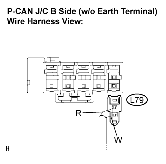 |
Disconnect the steering control ECU sub bus line connector (L79) from the P-CAN J/C B side (w/o earth terminal).
|
Measure the resistance according to the value(s) in the table below.
| Tester connection | Condition | Specified value |
| L16-6 (CANH) - L16-14 (CANL) | Engine Switch off | 54 to 69 Ω |
|
| ||||
| NG | |
| 36.CONNECT CONNECTOR |
Reconnect the steering control ECU sub bus line connector (L79) to the P-CAN J/C B side (w/o earth terminal).
| NEXT | |
| 37.CHECK CAN BUS LINES FOR SHORT CIRCUIT (POWER STEERING ECU SUB BUS LINE) |
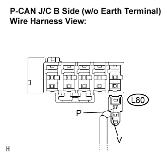 |
Disconnect the power steering ECU sub bus line connector (L80) from the P-CAN J/C B side (w/o earth terminal).
|
Measure the resistance according to the value(s) in the table below.
| Tester connection | Condition | Specified value |
| L16-6 (CANH) - L16-14 (CANL) | Engine Switch off | 54 to 69 Ω |
|
| ||||
| NG | |
| 38.CONNECT CONNECTOR |
Reconnect the power steering ECU sub bus line connector (L80) to the P-CAN J/C B side (w/o earth terminal).
| NEXT | |
| 39.CHECK CAN BUS LINES FOR SHORT CIRCUIT (ABSORBER CONTROL ECU SUB BUS LINE) |
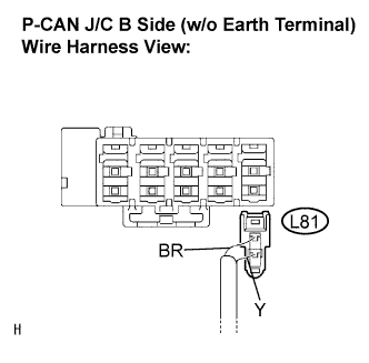 |
Disconnect the absorber control ECU sub bus line connector (L81) from the P-CAN J/C B side (w/o earth terminal).
|
Measure the resistance according to the value(s) in the table below.
| Tester connection | Condition | Specified value |
| L16-6 (CANH) - L16-14 (CANL) | Engine Switch off | 54 to 69 Ω |
|
| ||||
| NG | |
| 40.CONNECT CONNECTOR |
Reconnect the absorber control ECU sub bus line connector (L81) to the P-CAN J/C B side (w/o earth terminal).
| NEXT | |
| 41.CHECK CAN BUS LINES FOR SHORT CIRCUIT (CLEARANCE WARNING ECU SUB BUS LINE) |
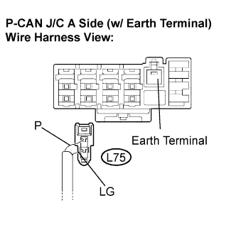 |
Disconnect the clearance warning ECU sub bus line connector (L75) from the P-CAN J/C A side (w/ earth terminal).
|
Measure the resistance according to the value(s) in the table below.
| Tester connection | Condition | Specified value |
| L16-6 (CANH) - L16-14 (CANL) | Engine Switch off | 54 to 69 Ω |
|
| ||||
| NG | |
| 42.CONNECT CONNECTOR |
Reconnect the clearance warning ECU sub bus line connector (L75) to the P-CAN J/C A side (w/ earth terminal).
| NEXT | |
| 43.CHECK CAN BUS LINES FOR SHORT CIRCUIT (TELEVISION CAMERA ECU SUB BUS LINE) |
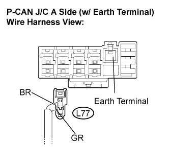 |
Disconnect the television camera ECU sub bus line connector (L77) from the P-CAN J/C A side (w/ earth terminal).
|
Measure the resistance according to the value(s) in the table below.
| Tester connection | Condition | Specified value |
| L16-6 (CANH) - L16-14 (CANL) | Engine Switch off | 54 to 69 Ω |
|
| ||||
| NG | |
| 44.CONNECT CONNECTOR |
Reconnect the television camera ECU sub bus line connector (L77) to the P-CAN J/C A side (w/ earth terminal).
| NEXT | |
| 45.CHECK CAN BUS LINES FOR SHORT CIRCUIT (NETWORK GATEWAY ECU SUB BUS LINE) |
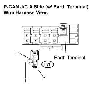 |
Disconnect the network gateway ECU sub bus line connector (L76) from the P-CAN J/C A side (w/ earth terminal).
|
Measure the resistance according to the value(s) in the table below.
| Tester connection | Condition | Specified value |
| L16-6 (CANH) - L16-14 (CANL) | Engine Switch off | 54 to 69 Ω |
|
| ||||
| NG | ||
| ||
| 46.CONNECT CONNECTOR |
Reconnect the steering control ECU sub bus line connector (L79) to the P-CAN J/C B side (w/o earth terminal).
| NEXT | |
| 47.CHECK CAN BUS LINES FOR SHORT CIRCUIT (STEERING CONTROL ECU SUB BUS LINE) |
Disconnect the steering control ECU connector (L70).
|
Measure the resistance according to the value(s) in the table below.
| Tester connection | Condition | Specified value |
| L16-6 (CANH) - L16-14 (CANL) | Engine Switch off | 54 to 69 Ω |
|
| ||||
| NG | ||
| ||
| 48.CONNECT CONNECTOR |
Reconnect the power steering ECU sub bus line connector (L80) to the P-CAN J/C B side (w/o earth terminal).
| NEXT | |
| 49.CHECK CAN BUS LINES FOR SHORT CIRCUIT (POWER STEERING ECU SUB BUS LINE) |
Disconnect the power steering ECU connector (A24).
|
Measure the resistance according to the value(s) in the table below.
| Tester connection | Condition | Specified value |
| L16-6 (CANH) - L16-14 (CANL) | Engine Switch off | 54 to 69 Ω |
|
| ||||
| NG | ||
| ||
| 50.CONNECT CONNECTOR |
Reconnect the absorber control ECU sub bus line connector (L81) to the P-CAN J/C B side (w/o earth terminal).
| NEXT | |
| 51.CHECK CAN BUS LINES FOR SHORT CIRCUIT (ABSORBER CONTROL ECU SUB BUS LINE) |
Disconnect the absorber control ECU connector (L72).
|
Measure the resistance according to the value(s) in the table below.
| Tester connection | Condition | Specified value |
| L16-6 (CANH) - L16-14 (CANL) | Engine Switch off | 54 to 69 Ω |
|
| ||||
| NG | ||
| ||
| 52.CONNECT CONNECTOR |
Reconnect the clearance warning ECU sub bus line connector (L75) to the P-CAN J/C A side (w/ earth terminal).
| NEXT | |
| 53.CHECK CAN BUS LINES FOR SHORT CIRCUIT (CLEARANCE WARNING ECU SUB BUS LINE) |
Disconnect the clearance warning ECU connector (A40).
|
Measure the resistance according to the value(s) in the table below.
| Tester connection | Condition | Specified value |
| L16-6 (CANH) - L16-14 (CANL) | Engine Switch off | 54 to 69 Ω |
|
| ||||
| NG | ||
| ||
| 54.CONNECT CONNECTOR |
Reconnect the television camera ECU sub bus line connector (L77) to the P-CAN J/C A side (w/ earth terminal).
| NEXT | |
| 55.CHECK CAN BUS LINES FOR SHORT CIRCUIT (TELEVISION CAMERA ECU SUB BUS LINE) |
Disconnect the television camera ECU connector (L64).
|
Measure the resistance according to the value(s) in the table below.
| Tester connection | Condition | Specified value |
| L16-6 (CANH) - L16-14 (CANL) | Engine Switch off | 54 to 69 Ω |
|
| ||||
| NG | ||
| ||
| 56.CONNECT CONNECTOR |
Reconnect the network gateway ECU sub bus line connector (L76) to the P-CAN J/C A side (w/ earth terminal).
| NEXT | |
| 57.CHECK CAN BUS LINES FOR SHORT CIRCUIT (NETWORK GATEWAY ECU SUB BUS LINE) |
Disconnect the network gateway ECU connector (L66).
|
Measure the resistance according to the value(s) in the table below.
| Tester connection | Condition | Specified value |
| L16-6 (CANH) - L16-14 (CANL) | Engine Switch off | 54 to 69 Ω |
|
| ||||
| NG | ||
| ||
