CAN COMMUNICATION SYSTEM > Check CAN Bus Line (LHD Models) |
| 1.CHECK CAN BUS MAIN LINE (MAIN BUS LINE FOR DISCONNECTION, BUS LINES FOR SHORT CIRCUIT) |
Turn the engine switch off.
 |
Measure the resistance according to the value(s) in the table below.
| Tester Connection | Condition | Specified Value | Result |
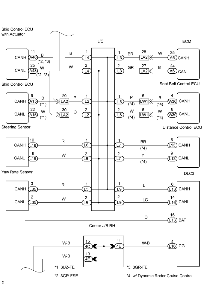
| L16-6 (CANH) - L16-14 (CANL) | Engine switch off | 54 to 69 Ω | OK |
| L16-6 (CANH) - L16-14 (CANL) | Engine switch off | 69 Ω or more | NG-A |
| L16-6 (CANH) - L16-14 (CANL) | Engine switch off | 54 Ω or less | NG-B |
|
| ||||
|
| ||||
| OK | |
| 2.CHECK CAN BUS LINE FOR SHORT TO +B |
 |
Measure the resistance according to the value(s) in the table below.
| Tester Connection | Condition | Specified Value |
| L16-6 (CANH) - L16-16 (BAT) | Engine switch off | 1 MΩ or more |
| L16-14 (CANL) - L16-16 (BAT) | Engine switch off | 1 MΩ or more |
|
| ||||
| OK | |
| 3.CHECK CAN BUS LINE FOR SHORT TO GND |
 |
Measure the resistance according to the value(s) in the table below.
| Tester Connection | Condition | Specified Value |
| L16-6 (CANH) - L16-16 (BAT) | Engine switch off | 1 MΩ or more |
| L16-14 (CANL) - L16-16 (BAT) | Engine switch off | 1 MΩ or more |
|
| ||||
| OK | ||
| ||
