RADIO ANTENNA CORD > REMOVAL |
| 1. SET RADIO RECEIVER ASSEMBLY TO SHIPMENT MODE |
Remove all discs and tapes.
Turn the engine switch off.
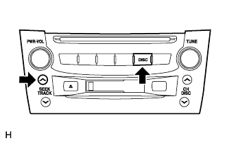 |
While simultaneously pressing the "SEEK UP" and "DISC" switches, turn the engine switch on (ACC).
 |
Turn the engine switch off.
| 2. DISCONNECT CABLE FROM NEGATIVE BATTERY TERMINAL |
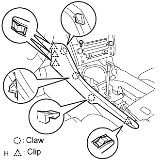
| 3. REMOVE FRONT CONSOLE UPPER PANEL GARNISH |
 |
Using a clip remover, detach the claws and remove the garnish.
| 4. REMOVE CONSOLE UPPER PANEL ASSEMBLY |
 |
Twist the shift lever knob in the direction indicated by the arrow and remove it.
 |
Using a screwdriver, detach the 9 clips.
Remove the ash receptacle and then disconnect the connector.
| 5. REMOVE INSTRUMENT PANEL FINISH PANEL END LH |
 |
Remove the screw.
Using a screwdriver, detach the 4 clips and 3 claws.
Remove the finish panel end.
| 6. REMOVE INSTRUMENT PANEL FINISH PANEL END RH |
 |
Remove the screw.
Using a screwdriver, detach the 3 clips and 3 claws.
Remove the finish panel end.
| 7. REMOVE CONSOLE BOX PLATE |
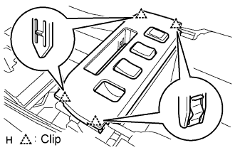 |
Using a screwdriver, detach the 4 clips.
Remove the console box plate and then disconnect the connector.
| 8. REMOVE CONSOLE BOX REGISTER ASSEMBLY |
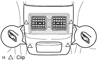 |
Using a screwdriver, detach the 4 clips and remove the register.
| 9. REMOVE CONSOLE BOX |
 |
Remove the 4 bolts and 2 screws.
Remove the console box and then disconnect the connector.
| 10. REMOVE MULTI-DISPLAY WITH RADIO RECEIVER ASSEMBLY |
 |
Remove the 4 bolts.
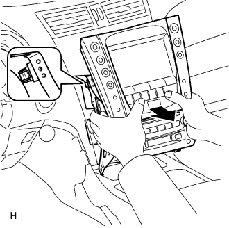 |
Pull the multi-display with radio receiver to detach the 2 clips on the backside of the multi-display.
Disconnect the connectors and remove the multi-display with radio receiver.
| 11. CONFIRM RADIO RECEIVER ASSEMBLY SHIPMENT MODE |
 |
Look at the backside of the radio receiver and check that a metal plate can be seen through the hole near the "SHIP" mark.
| 12. REMOVE ANTENNA CORD SUB-ASSEMBLY |
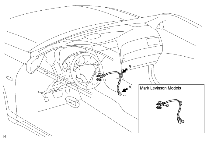
Disconnect the connector labeled A.
Detach the clip labeled B and remove the antenna cord.
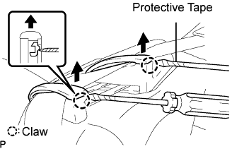
| 13. REMOVE REAR SEAT CUSHION ASSEMBLY |
 |
Detach the seat cushion's 2 front hooks from the vehicle body.
Choose a hook to detach first. Place your hands near the hook as shown in the illustration. Then lift the seat cushion to detach the hook.
Repeat for the other hook.
Detach the seat cushion's 2 rear hooks from the seatback.
Remove the seat cushion.
| 14. REMOVE REAR SEAT HEADREST ASSEMBLY LH AND RH |
| 15. REMOVE REAR SEAT HEADREST ASSEMBLY CENTER |
| 16. REMOVE REAR SEATBACK ASSEMBLY |

Using a screwdriver, detach the claws and remove the 2 rear seat covers.
 |
Using a screwdriver, detach the claw to open the cap of the 3 rear seat shoulder belt guides.
Remove the bolt and floor anchor part.
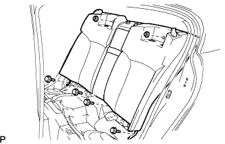 |
Remove the 4 bolts and 2 nuts.
Remove the seatback.
| 17. REMOVE REAR DOOR SCUFF PLATE RH |
| 18. REMOVE REAR SEAT SIDE GARNISH RH |
| 19. REMOVE NO. 2 ANTENNA CORD SUB-ASSEMBLY |


Disconnect the connectors labeled A.
Remove the 3 bolts labeled B.
Detach the antenna cord protector's 3 clips labeled C from the floor stud bolts.
Detach the 6 clips labeled D and remove the antenna cord.
