NAVIGATION ANTENNA > REMOVAL |
| 1. SET RADIO RECEIVER ASSEMBLY TO SHIPMENT MODE |
Remove all discs and tapes.
Turn the engine switch off.
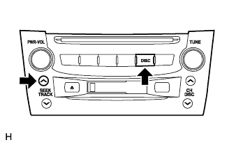 |
While simultaneously pressing the "SEEK UP" and "DISC" switches, turn the engine switch on (ACC).
 |
Turn the engine switch off.
| 2. DISCONNECT CABLE FROM NEGATIVE BATTERY TERMINAL |
| 3. REMOVE FRONT DOOR SCUFF PLATE LH |
 |
Using a moulding remover, detach the 5 claws and remove the scuff plate.
| 4. REMOVE FRONT DOOR SCUFF PLATE RH |
| 5. REMOVE FRONT DOOR OPENING TRIM COVER LH |
Using a moulding remover, detach the 3 claws and remove the trim cover.
| 6. REMOVE FRONT DOOR OPENING TRIM COVER RH |
| 7. REMOVE NO. 3 STEERING WHEEL COVER LOWER |
 |
Using a screwdriver, remove the steering wheel No.3 cover lower.
| 8. REMOVE NO. 2 STEERING WHEEL COVER LOWER |
 |
Using a screwdriver, remove the steering wheel No.2 cover lower.
| 9. REMOVE STEERING PAD |
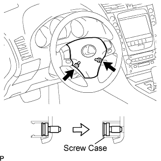 |
Using a "torx" socket wrench (T30), loosen the 2 "torx" screws until the groove along the screw circumference catches on the screw case.
 |
Pull out the steering pad from the steering wheel assembly and support the steering pad with one hand as shown in the illustration.
Disconnect the horn connector.
Disconnect the 2 connectors and remove the steering pad.
| 10. REMOVE STEERING WHEEL ASSEMBLY |
Remove the steering wheel assembly set nut.
Put matchmarks on the steering wheel assembly and main shaft assembly.
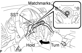 |
Using SST, remove the steering wheel assembly.
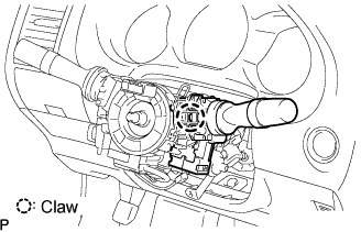
| 11. REMOVE STEERING COLUMN COVER |
 |
Remove the 3 screws.
Disengage the 2 claws to remove the steering column cover lower.
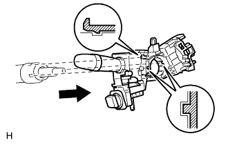
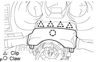 |
Disengage the 4 clips to separate the steering column cover upper.
Disengage the claw to remove the steering column cover upper.
| 12. REMOVE SPIRAL CABLE WITH STEERING SENSOR |
 |
Disconnect the connectors from the spiral cable with steering sensor.
Disengage the 3 claws and remove the spiral cable with steering sensor.
| 13. REMOVE WINDSHIELD WIPER SWITCH ASSEMBLY |
 |
Disconnect the connector.
Detach the claw and remove the wiper switch.
| 14. REMOVE HEADLIGHT DIMMER SWITCH ASSEMBLY |
 |
Disconnect the connector.
 |
Detach the clamp from the dimmer switch as shown in the illustration.
Detach the claw and remove the dimmer switch as shown in the illustration.
| 15. REMOVE FRONT CONSOLE UPPER PANEL GARNISH |
 |
Using a clip remover, detach the claws and remove the garnish.
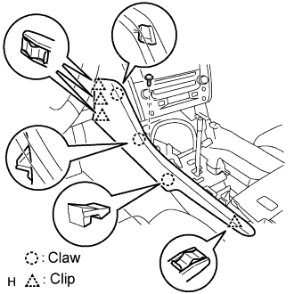
| 16. REMOVE CONSOLE UPPER PANEL ASSEMBLY |
 |
Twist the shift lever knob in the direction indicated by the arrow and remove it.
 |
Using a screwdriver, detach the 9 clips.
Remove the ash receptacle and then disconnect the connector.
| 17. REMOVE INSTRUMENT PANEL FINISH PANEL END LH |
 |
Remove the screw.
Using a screwdriver, detach the 4 clips and 3 claws.
Remove the finish panel end.
| 18. REMOVE INSTRUMENT PANEL FINISH PANEL END RH |
 |
Remove the screw.
Using a screwdriver, detach the 3 clips and 3 claws.
Remove the finish panel end.
| 19. REMOVE CONSOLE BOX PLATE |
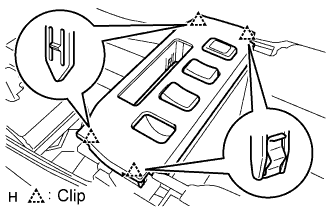 |
Using a screwdriver, detach the 4 clips.
Remove the console box plate and then disconnect the connector.
| 20. REMOVE CONSOLE BOX REGISTER ASSEMBLY |
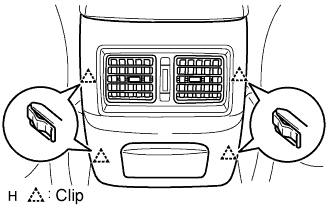 |
Using a screwdriver, detach the 4 clips and remove the register.
| 21. REMOVE CONSOLE BOX |
 |
Remove the 4 bolts and 2 screws.
Remove the console box and then disconnect the connector.
| 22. REMOVE INSTRUMENT CLUSTER FINISH PANEL SUB-ASSEMBLY |
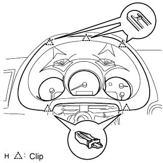 |
Using a screwdriver, detach the 5 clips.
Remove the cluster finish panel and then disconnect the connector.
| 23. REMOVE COMBINATION METER ASSEMBLY |
 |
Remove the 4 screws.
Disconnect the connector and remove the combination meter.
| 24. REMOVE INSTRUMENT SIDE PANEL LH |
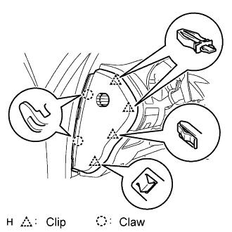 |
Using a screwdriver, detach the 2 claws and 4 clips, and remove the side panel.
| 25. REMOVE INSTRUMENT SIDE PANEL RH |
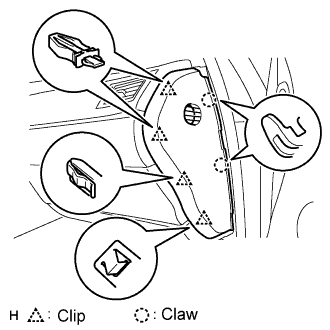 |
Using a screwdriver, detach the 2 claws and 4 clips, and remove the side panel.
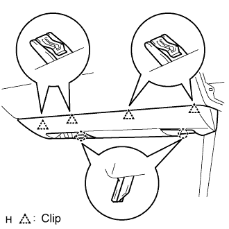
| 26. REMOVE NO. 1 INSTRUMENT PANEL UNDER COVER SUB-ASSEMBLY |
 |
Remove the 2 screws.
Detach the 2 claws.
Remove the under cover and then disconnect the connector.
| 27. REMOVE NO. 1 INSTRUMENT PANEL SAFETY PAD SUB-ASSEMBLY |
 |
Using a screwdriver, detach the 8 clips and claw.
Remove the hood lock control cable from the safety pad.
Remove the safety pad.
| 28. REMOVE DRIVER SIDE KNEE AIRBAG ASSEMBLY |
 |
Remove the 4 bolts and driver side knee airbag assembly.
Disconnect the connector.
| 29. REMOVE INTEGRATION CONTROL AND PANEL ASSEMBLY |
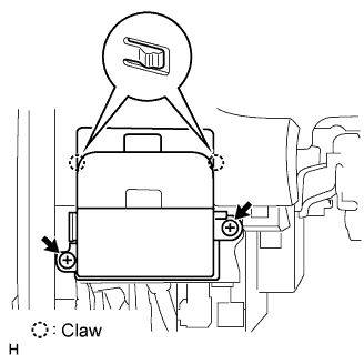 |
Remove the 2 screws.
Using a screwdriver, detach the 2 claws.
Remove the control panel and then disconnect the connector.
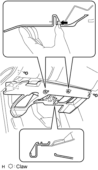
| 30. REMOVE NO. 2 INSTRUMENT PANEL UNDER COVER SUB-ASSEMBLY |
 |
Using a screwdriver, detach the 4 clips.
Disconnect the connector and clamp, and remove the under cover.
| 31. REMOVE FRONT PASSENGER SIDE KNEE AIRBAG ASSEMBLY |
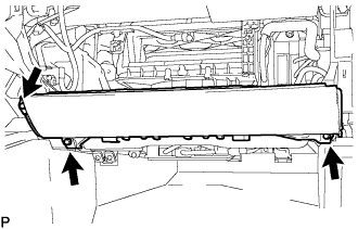 |
Remove the 3 bolts and front passenger side knee airbag assembly.
Disconnect the connector.
| 32. REMOVE GLOVE COMPARTMENT DOOR SUB-ASSEMBLY |
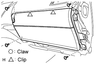 |
Remove the 4 screws.
Detach the 2 clips and claw.
Disconnect the connector and clamp.
Remove the glove compartment door.
| 33. REMOVE FRONT PILLAR GARNISH LH |
 |
Detach the clip labeled A from the vehicle body. Pull the pillar garnish so that the tip of clip B locks in the pillar garnish's hole.
Using needle-nose pliers, rotate clip B 90° and remove the pillar garnish.
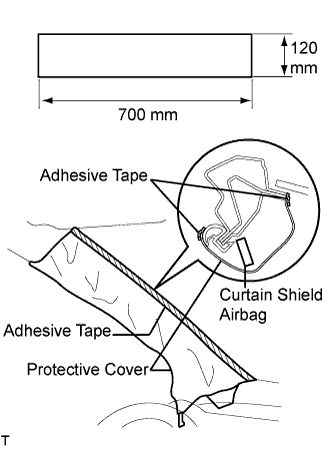 |
Protect the curtain shield airbag.
Thoroughly cover the airbag with a cloth or nylon sheet that is 700 mm (27.56 in.) x 120 mm (4.72 in.) and fix the ends of the cover with adhesive tape, as shown in the illustration.
| 34. REMOVE FRONT PILLAR GARNISH RH |
| 35. REMOVE MULTI-DISPLAY WITH RADIO RECEIVER ASSEMBLY |
 |
Remove the 4 bolts.
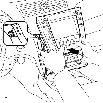 |
Pull the multi-display with radio receiver to detach the 2 clips on the backside of the multi-display.
Disconnect the connectors and remove the multi-display with radio receiver.
| 36. CONFIRM RADIO RECEIVER ASSEMBLY SHIPMENT MODE SETTING |
 |
Look at the backside of the radio receiver and check that a metal plate can be seen through the hole near the "SHIP" mark.
| 37. REMOVE INSTRUMENT PANEL SAFETY PAD SUB-ASSEMBLY |
 |
w/ Navigation system:
Remove the navigation ECU.
Remove the 3 bolts and navigation ECU.
Disconnect the connectors.
Remove the 4 nuts and center junction block RH and LH.
Remove the 4 bolts, nut and 2 clips.
Remove the 2 bolts from the passenger airbag.
Disconnect the connectors and clamps.
Detach the 5 clips and remove the safety pad.

| 38. REMOVE SIDE NO. 1 DEFROSTER NOZZLE DUCT |
 |
Remove the screw and duct.
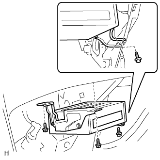
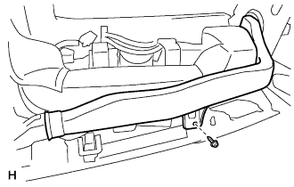
| 39. REMOVE NO. 1 HEATER TO REGISTER DUCT |
 |
Remove the 4 screws and duct.
| 40. REMOVE NAVIGATION ANTENNA |
 |
Remove the 3 screws and detach the 4 clips to remove the antenna.
