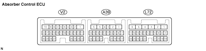
Connector V2:
Symbols
(Terminal No.)
| Wiring Color
| Terminal Description
| Condition
| Specified Condition
|
RAR+ (2) - Body ground
| W - Body ground
| Rear right actuator output
| Engine switch off
| 12.0 to 12.8 Ω
|
RAR- (3) - Body ground
| V - Body ground
| Rear right actuator output
| Engine switch off
| 12.0 to 12.8 Ω
|
RBR+ (4) - Body ground
| GR - Body ground
| Rear right actuator output
| Engine switch off
| 12.0 to 12.8 Ω
|
RBR- (5) - Body ground
| Y - Body ground
| Rear right actuator output
| Engine switch off
| 12.0 to 12.8 Ω
|
RAL+ (6) - Body ground
| B - Body ground
| Rear left actuator output
| Engine switch off
| 12.0 to 12.8 Ω
|
RAL- (7) - Body ground
| G - Body ground
| Rear left actuator output
| Engine switch off
| 12.0 to 12.8 Ω
|
RBL+ (8) - Body ground
| R - Body ground
| Rear left actuator output
| Engine switch off
| 12.0 to 12.8 Ω
|
RBL- (9) - Body ground
| W - Body ground
| Rear left actuator output
| Engine switch off
| 12.0 to 12.8 Ω
|
SGL3 (11) - Body ground
| LG - Body ground
| Front acceleration sensor ground
| Engine switch off
| Below 1 Ω
|
SGR3 (12) - Body ground
| BR - Body ground
| Rear acceleration sensor ground
| Engine switch off
| Below 1 Ω
|
SBR3 (15) - SGR3 (12)
| P - BR
| Rear acceleration sensor power supply
| Engine switch on (IG)
| 4.75 to 5.25 V
|
SBL3 (16) - SGL3 (11)
| O - LG
| Front acceleration sensor power supply
| Engine switch on (IG)
| 4.75 to 5.25 V
|
SGRR (27) - SGR3 (12)
| SB - BR
| Front acceleration sensor signal
| Engine switch on (IG), vehicle stationary condition
| Aprox. 2.25 V
|
SGFL (29) - SGL3 (11)
| L - LG
| Rear acceleration sensor signal
| Engine switch on (IG), vehicle stationary condition
| Aprox. 2.25 V
|
Connector L72:
Symbols
(Terminal No.)
| Wiring Color
| Terminal Description
| Condition
| Specified Condition
|
B (1) - GND (4)
| B - W-B
| Power supply
| Engine switch on (IG)
| 10 to 14 V
|
GND (4) - Body ground
| W-B - Body ground
| Absorber control ECU ground
| Engine switch off
| Below 1 Ω
|
CANH (7) - CANL (8)
| BR - Y
| CAN communication system
| Engine switch off
| Below 1 Ω
|
SW1 (9) - Body ground
| V - Body ground
| Absorber control switch input
| Engine switch on (IG), absorber control switch ON
| 10 to 14 V
|
SW1 (9) - Body ground
| V - Body ground
| Absorber control switch input
| Engine switch on (IG), absorber control switch OFF
| 0 to 1.5 V
|
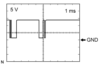
SIL (13) - Body ground
| SB - Body ground
| Diagnostic communication terminal
| Engine switch on (IG), connect intelligent tester to the DLC3
| Pulse generation
(see waveform 1)
|