ADAPTIVE VARIABLE SUSPENSION SYSTEM > DIAGNOSIS SYSTEM |
| DIAGNOSIS SYSTEM |
Inspect the battery voltage.
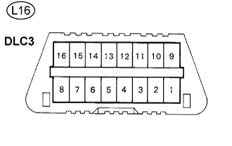 |
Check DLC3.
The absorber control ECU uses CAN and ISO 9141-2 (Euro-OBD) as its communication protocol. The terminal arrangement of the DLC3 complies with ISO 15031-3 and matches the ISO 9141-2 format.
Verify the conditions listed in the table below:
| Symbols (Terminal No.) | Terminal Description | Condition | Specified Condition |
| SIL (2) - SG (5) | Bus "+" line | During communication | Pulse generation |
| CG (4) - Body ground | Chassis ground | Always | Below 1 Ω |
| SG (5) - Body ground | Signal ground | Always | Below 1 Ω |
| BAT (16) - Body ground | Battery positive | Always | 11 to 14 V |
| CANH (6) - CANL (14) | HIGH-level CAN bus line | Engine switch off | 54 to 67 Ω |
| CANH (6) - Battery positive | HIGH-level CAN bus line | Engine switch off | 1 MΩ or higher |
| CANH (6) - CG (4) | HIGH-level CAN bus line | Engine switch off | 3 KΩ or higher |
| CANL (14) - Battery positive | LOW-level CAN bus line | Engine switch off | 1 MΩ or higher |
| CANL (14) - CG (4) | LOW-level CAN bus line | Engine switch off | 3 KΩ or higher |
DTCs (Normal mode)
DTCs are memorized in the absorber control ECU and read by using the intelligent tester (Click here).
Test Mode (Signal Check)
By switching from normal mode into Test Mode, you can inspect the absorber control switch and each acceleration sensor (Click here).
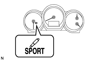 |
Check the absorber control indicator light.
Turn the engine switch on (IG).
Check that the absorber control indicator light comes on for 2 seconds.
If the indicator light check result is not normal, proceed to troubleshooting for the absorber control indicator light circuit below.
| Trouble area | See Procedure |
| Absorber control indicator light (Remains on) |
Click here
|
| Absorber control indicator light (Does not come on) |
Click here
|
