SOLAR SENSOR > ON-VEHICLE INSPECTION |
| 1. CHECK AIR CONDITIONING SOLAR SENSOR |
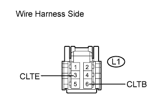 |
Disconnect the A/C solar sensor connector.
Measure the resistance according to the value(s) in the table below.
| Tester Connection | Condition | Specified Condition |
| L1-3 (CLTE) - Body ground | Always | Below 1 Ω |
Measure the voltage according to the value(s) in the table below.
| Tester Connection | Condition | Specified Condition |
| L1-6 (CLTB) - L1-3 (CLTE) | Engine switch on (IG) | 10 to 14 V |
| 2. INSPECT SOLAR SENSOR |
 |
Remove the A/C solar sensor with the connector still connected.
Apply battery voltage between terminals 6 (CLTB) and 3 (CLTE) of the A/C solar sensor.
Measure the voltage according to the value(s) in the table below.
| Tester Connection | Condition | Specified Condition |
| 1 (TSL) - 3 (CLTE) | Sensor is subjected to electric light | 0.8 to 4.3 V |
| 1 (TSL) - 3 (CLTE) | Sensor is covered by a cloth | Below 0.8 V |
