CONDENSER > INSTALLATION |
| 1. INSTALL COOLER CONDENSER ASSEMBLY |
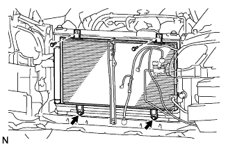 |
Install the cooler condenser with the 4 bolts.
| 2. INSTALL DISCHARGE HOSE SUB-ASSEMBLY |
 |
Remove the vinyl tape attached to the pipe and connecting part of the cooler condenser.
Sufficiently apply compressor oil to a new O-ring and the fitting surface of the pipe joint.
Install the O-ring on the discharge hose.
Install the discharge hose on the cooler condenser with the bolt.
| 3. INSTALL LIQUID TUBE SUB-ASSEMBLY A |
 |
Remove the vinyl tape attached to the pipe and connecting part of the cooler condenser.
Sufficiently apply compressor oil to a new O-ring and the fitting surface of the pipe joint.
Install the O-ring on the liquid tube.
Install the liquid tube on the cooler condenser with the bolt.
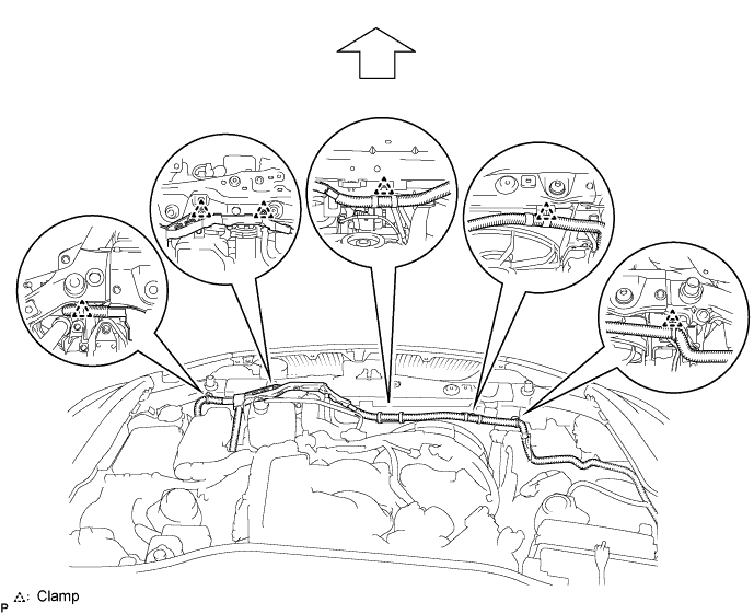
| 4. INSTALL UPPER RADIATOR SUPPORT SUB-ASSEMBLY |
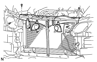 |
Install the radiator support with the 5 bolts.
Attach the 6 clamps and install the wire harness.
| 5. INSTALL HOOD LOCK ASSEMBLY |
 |
Apply MP grease to the sliding areas of the lock.
 |
Install the hood lock.
Install the 2 bolts and nut.
Install a new cap.
Connect the hood lock control cable.
| 6. INSTALL HOOD LOCK CONTROL CABLE COVER |
 |
Attach the claw and install the cable cover.
Install the 3 screws.
| 7. INSTALL RADIATOR SUPPORT OPENING COVER |
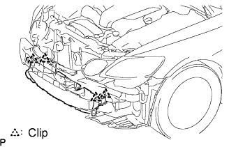 |
Install the cover with the 4 clips.
| 8. INSTALL MILLIMETER WAVE RADAR SENSOR ASSEMBLY (w/ Dynamic Radar Cruise Control System) |
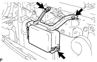 |
Install the sensor with the 3 bolts.
Connect the connector.
| 9. INSTALL FRONT BUMPER COVER |
Connect the ultrasonic sensor connector.
 |
Attach the 3 claws on the LH side.
Attach the 3 claws on the RH side.
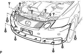 |
Install the bumper cover with the 2 clips, 6 screws and 5 bolts.
| 10. INSTALL NO. 1 AIR CLEANER INLET |
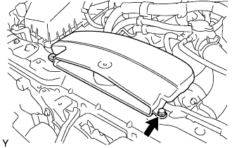 |
Install the air cleaner inlet with the bolt.
| 11. INSTALL ENGINE ROOM SIDE COVER LH |
 |
Install the side cover with the 3 clips.
| 12. INSTALL ENGINE ROOM SIDE COVER RH |
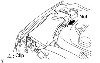 |
Install the side cover with the 2 clips and nut.
| 13. CONNECT CABLE TO NEGATIVE BATTERY TERMINAL |
| 14. CHARGE REFRIGERANT |
Perform vacuum purging using a vacuum pump.
Charge refrigerant HFC-134a (R134a).

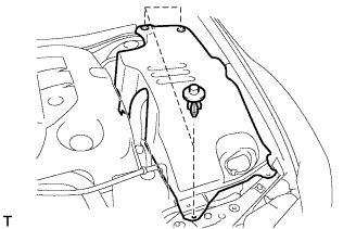
| 15. INSTALL COOL AIR INTAKE DUCT SEAL |
 |
Install the intake duct seal with the 7 clips.
| 16. WARM UP ENGINE |
Warm up the engine at less than 1,850 rpm for 2 minutes or more after charging the refrigerant.
| 17. CHECK FOR LEAKAGE OF REFRIGERANT |
After recharging the refrigerant gas, check for refrigerant gas leakage using a halogen leak detector.
Perform the operation under these conditions:
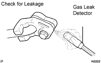 |
Using a gas leak detector, check the refrigerant line for leakage.
If a gas leak is not detected on the drain hose, remove the blower motor control (blower resistor) from the cooling unit. Insert the gas leak detector sensor into the unit and perform the test.
Disconnect the connector and leave the pressure switch on for approximately 20 minutes. Bring the gas leak detector close to the pressure switch and perform the test.
| 18. PERFORM INITIALIZATION |
Perform initialization (Click here).
