CAMSHAFT TIMING OIL CONTROL VALVE ASSEMBLY > INSTALLATION |
| 1. INSTALL CAMSHAFT TIMING OIL CONTROL VALVE ASSEMBLY LH |
 |
Install a new O-ring to the oil control valve.
Install the oil control valve with the bolt.
Connect the oil control valve connector.
| 2. INSTALL CAMSHAFT TIMING OIL CONTROL VALVE ASSEMBLY RH |
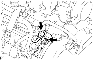 |
Install a new O-ring to the oil control valve.
Install the oil control valve with the bolt.
Connect the oil control valve connector.
| 3. INSTALL INTAKE AIR CONNECTOR PIPE |
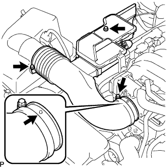 |
Install the intake air connector pipe with the bolt and 2 hose clamps.
Connect the air hose and No. 1 ventilation hose.
| 4. INSTALL NO. 1 AIR CLEANER INLET |
Install the air cleaner inlet with the bolt.
| 5. INSTALL V-BANK COVER |
Install the V-bank cover with the 2 nuts.
| 6. INSTALL ENGINE ROOM SIDE COVER LH |
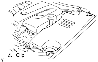 |
Install the side cover with the 3 clips.
| 7. INSTALL ENGINE ROOM SIDE COVER RH |
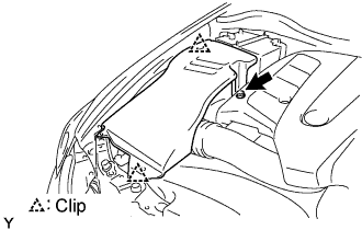 |
Install the side cover with the 2 clips and nut.
| 8. INSTALL COOL AIR INTAKE DUCT SEAL |
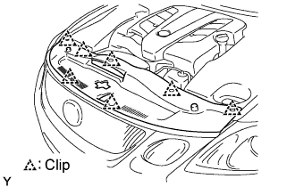 |
Install the intake duct seal with the 7 clips.
| 9. CONNECT CABLE TO NEGATIVE BATTERY TERMINAL |
| 10. PERFORM INITIALIZATION |
Perform initialization (Click here).
