INTEGRATION RELAY > INSPECTION |
| 1. INSPECT INTEGRATION RELAY |
 |
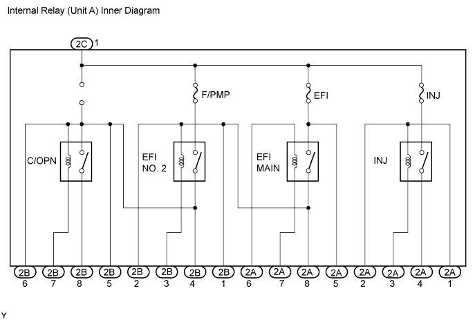
Measure the resistance of the C/OPN relay.
Connect the battery's positive (+) lead to terminal 2A-8 and negative (-) lead to terminal 2B-33. Using an ohmmeter, check resistance between the terminals when battery voltage is applied between the terminals.
| Tester Connection | Specified Condition |
| 2C-2 - 2B-7 | Below 1 Ω |
| 2C-1 - 2B-8 | 10 kΩ or higher |
Connect the battery's positive (+) lead to terminals 2A-8 and 2C-1, and negative (-) lead to terminal 2B-3 and 2B-7. Using an ohmmeter, check that there is resistance between terminals 2C-1 and 2B-8 when battery voltage is applied between the terminals.
| Tester Connection | Specified Condition |
| 2C-1 - 2B-8 | Below 1 Ω (when battery voltage is applied to terminals 2A-8 and 2B-3, and 2C-1 and 2B-7) |
 |
Measure the resistance of the EFI MAIN relay.
Remove the EFI fuse. Using an ohmmeter, measure the resistance between the terminals.
| Tester Connection | Specified Condition |
| 2A-6 - 2A-7 | Below 1 Ω |
| EFI fuse terminal 2 - 2A-8 | 10 kΩ or higher |
Connect the battery's positive (+) lead to terminal 2A-6 and negative (-) lead to terminal 2A-7. Using an ohmmeter, check that there is resistance between EFI fuse terminal 2 and terminal 2A-8 when battery voltage is applied between the terminals.
| Tester Connection | Specified Condition |
| EFI fuse terminal 2 - terminal 2A-8 | Below 1 Ω (when battery voltage is applied to terminals 2A-6 and 2A-7) |
 |
Measure the resistance of the EFI NO. 2 relay.
Using an ohmmeter, measure the resistance between the terminals.
| Tester Connection | Specified Condition |
| 2B-3 - 2A-8 | Below 1 Ω |
| 2B-7 - 2C-1 | 10 kΩ or higher |
Connect the battery's positive (+) lead to terminal 2A-8 and negative (-) lead to terminal 2B-3. Using an ohmmeter, check that there is resistance between terminals 2B-7 and 2C-1 when battery voltage is applied between the terminals.
| Tester Connection | Specified Condition |
| 2B-7 - 2C-1 | Below 1 Ω (when battery voltage is applied to terminals 2B-3 and 2A-8) |
 |
Measure the resistance of the EFI INJ relay.
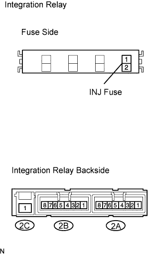
Remove the INJ fuse. Using an ohmmeter, measure the resistance between the terminals.
| Tester Connection | Specified Condition |
| 2A-1 - 2A-3 | Below 1 Ω |
| INJ fuse terminal 2 - C4 | 10 kΩ or higher |
Connect the battery's positive (+) lead to terminal 2A-1 and negative (-) lead to terminal 2A-3. Using an ohmmeter, check that there is resistance between INJ fuse terminals 2 and terminal 2A-4 when battery voltage is applied between the terminals.
| Tester Connection | Specified condition |
| INJ fuse terminal 2 - terminal 2A-4 | Below 1 Ω (when battery voltage is applied to terminals 2A-1 and 2A-3) |
