CRANKSHAFT POSITION SENSOR > INSTALLATION |
| 1. INSTALL CRANKSHAFT POSITION SENSOR |
 |
Apply a light coat of engine oil to a new O-ring of the sensor.
Install the sensor with the bolt.
Connect the sensor connector.
| 2. INSTALL COMPRESSOR ASSEMBLY |
 |
Using an E8 "torx" socket, install the compressor with the stud bolt.
 |
Install the compressor with the 3 bolts and nut.
| 3. INSTALL ENGINE UNDER COVER |
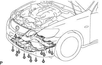 |
Install the under cover with the 10 bolts and 3 clips.
| 4. INSTALL V-RIBBED BELT |
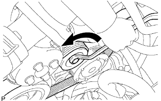 |
Install the V-ribbed belt.
While turning the belt tensioner counterclockwise, remove the bar.
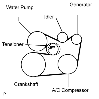 |
If it is difficult to install the V-ribbed belt, perform the following procedure.
Put the V-ribbed belt on everything except the tensioner pulley as shown in the illustration.
While releasing the belt tension by turning the belt tensioner counterclockwise, put the V-ribbed belt on the tensioner pulley.
| 5. INSTALL V-BANK COVER |
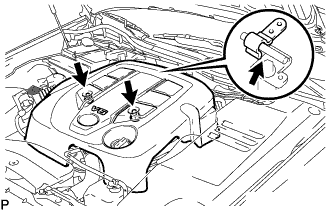 |
Install the V-bank cover with the 2 nuts.
| 6. INSTALL NO. 1 AIR CLEANER INLET |
Install the air cleaner inlet with the bolt.
| 7. INSTALL ENGINE ROOM SIDE COVER LH |
 |
Install the side cover with the 3 clips.
| 8. INSTALL ENGINE ROOM SIDE COVER RH |
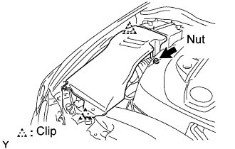 |
Install the side cover with the 2 clips and nut.
| 9. INSTALL COOL AIR INTAKE DUCT SEAL |
 |
Install the intake duct seal with the 7 clips.
| 10. CONNECT CABLE TO NEGATIVE BATTERY TERMINAL |
| 11. PERFORM INITIALIZATION |
Perform initialization (Click here).
