NAVIGATION SYSTEM > AVC-LAN Circuit between Multi-display and Television Camera ECU |

| 1.CHECK WIRE HARNESS (TELEVISION CAMERA ECU - MULTI-DISPLAY) |
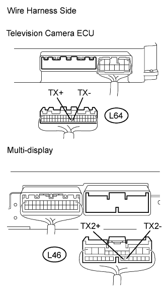 |
Disconnect the L64 ECU connector.
Disconnect the L46 multi-display connector.
Measure the resistance of the wire harness side connectors.
| Tester Connection | Condition | Specified Condition |
| L64-29 (TX+) - L46-18 (TX2+) | Always | Below 1 Ω |
| L64-30 (TX+) - L46-19 (TX2+) | Always | Below 1 Ω |
| L64-29 (TX+) - Body ground | Always | 10 kΩ or higher |
| L64-30 (TX+) - Body ground | Always | 10 kΩ or higher |
|
| ||||
| OK | ||
| ||
