THEFT DETERRENT SYSTEM > TERMINALS OF ECU |
| CHECK COWL SIDE JUNCTION BLOCK RH (MULTIPLEX NETWORK BODY ECU) |
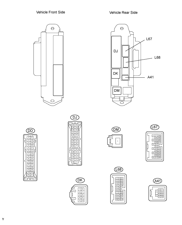
Disconnect the DD, DK, DJ and DM junction block connectors.
Measure the voltage and resistance of the wire harness side connectors.
| Symbols (Terminal No.) | Wiring Color | Terminal Description | Condition | Specified Condition |
| GND2 (DD-7) - Body ground | W-B - Body ground | Ground | Always | Below 1 Ω |
| BECU (DK-5) - Body ground | G-R - Body ground | Battery (power supply) | Always | 10 to 14 V |
| BATB (DJ-5) - Body ground | O - Body ground | Battery (power supply) | Always | 10 to 14 V |
| IG (DM-1) - Body ground | B - Body ground | Ignition power supply | Always | 10 to 14 V |
Reconnect the DD, DK, DJ and DM junction block connectors.
Measure the voltage of the connector.
| Symbols (Terminal No.) | Wiring Color | Terminal Description | Condition | Specified Condition |
| IND (L67-24) - Body ground | LG - Body ground | Security indicator signal | Security indicator illuminates or blinks when system is in armed state | 3 to 6 V |
| SH (A41-1) - Body ground*1 | W - Body ground | Security horn signal | Security horn is sounding (Theft deterrent system is in alarm sounding state) | Pulse generation |
| HAZ (L67-2) - Body ground | O - Body ground | Hazard warning light signal | System is in alarm sounding state | Pulse generation |
| SSCL (L67-12) - Body ground*2 | G - Body ground | Theft warning siren signal | Theft warning siren is sounding (Theft warning system is in alarm sounding state) | Pulse generation |
| CHECK ENGINE ROOM NO. 2 RELAY BLOCK, JUNCTION BLOCK (FRONT CONTROLLER) |

Disconnect the 2E, 2F and 2G front controller connectors.
Measure the voltage and resistance of the wire harness side connectors.
| Symbols (Terminal No.) | Wiring Color | Terminal Description | Condition | Specified Condition |
| 2E-4 - Body ground | G-R - Body ground | Battery power supply (ECU) | Always | 10 to 14 V |
| 2F-1 - Body ground | W-B - Body ground | Ground | Always | Below 1 Ω |
| 2G-3 - Body ground | W-L - Body ground | Engine hood courtesy switch signal | Engine hood closed | 10 kΩ or higher |
| 2G-3 - Body ground | W-L - Body ground | Engine hood courtesy switch signal | Engine hood open | Below 1 Ω |
Reconnect the 2E, 2F and 2G front controller connectors.
Measure the voltage of the connector.
| Symbols (Terminal No.) | Wiring Color | Terminal Description | Condition | Specified Condition |
| 2G-1 - Body ground | B - Body ground | Horn signal | Horn sounding | 10 to 14 V |
| 2G-1 - Body ground | B - Body ground | Horn signal | Horn sounding | Below 1 V |
| CHECK POWER SOURCE CONTROL ECU ASSEMBLY |

Disconnect the L73 ECU connector.
Measure the resistance and voltage of the wire harness side connector.
| Symbols (Terminal No.) | Wiring Color | Terminal Description | Condition | Specified Condition |
| AM1 (L73-33) - Body ground | R - Body ground | +B power supply | Always | 10 to 14 V |
| AM2 (L73-12) - Body ground | O - Body ground | +B power supply | Always | 10 to 14 V |
| GND2 (L73-6) - Body ground | W-B - Body ground | Ground | Always | Below 1 Ω |
